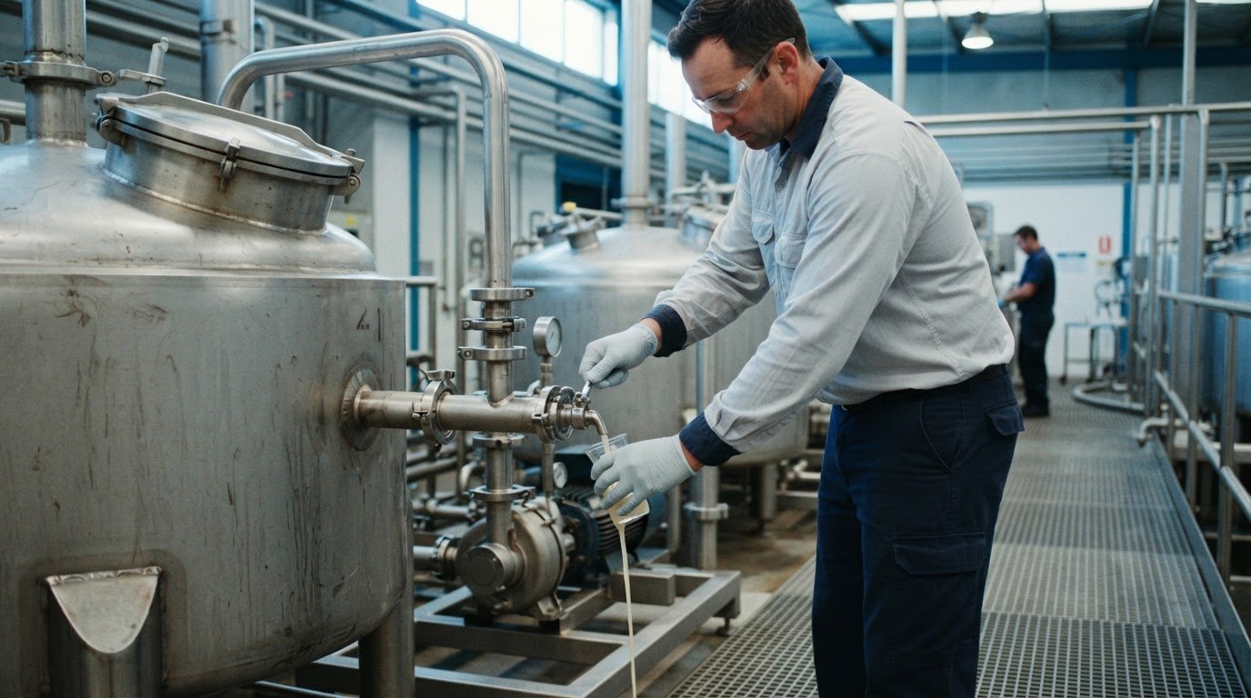
How to Achieve Batch Consistency With Quality by Design

The same recipe doesn’t guarantee the same batch when equipment, scale or process conditions change. Knowing how to achieve batch consistency means defining the product attributes that matter, controlling the process variables that affect them, and monitoring results during production rather than relying only on final testing.

It’s reasonable to focus on formulation, but mixing performance, equipment differences and scale-up can also affect batch uniformity. A consistent process therefore needs clear operating parameters, repeatable procedures and appropriate checks at each stage.

This article explains how Quality by Design connects critical quality attributes with critical process parameters, and how process monitoring and third-party testing can help identify variation. It also examines equipment comparability and scale-up, where machinery differences can change how a process behaves. Together, these methods provide a practical framework for understanding variation and building more reliable production from batch to batch.

Key Takeaways

  • Define the product attributes that matter, then identify and control the process conditions that can affect them.
  • Use batch records, trend analysis and change control to distinguish normal variation from a developing process issue.
  • Monitor key conditions during production to spot variation early, without assuming that equipment must be replaced.
  • Use independent testing to assess incoming materials, including purity, moisture and particle size, and support confidence in batch results.
  • During scale-up or equipment changes, assess comparability because differences in mixing and processing can affect product uniformity.

Quality by Design, critical quality attributes and critical process parameters

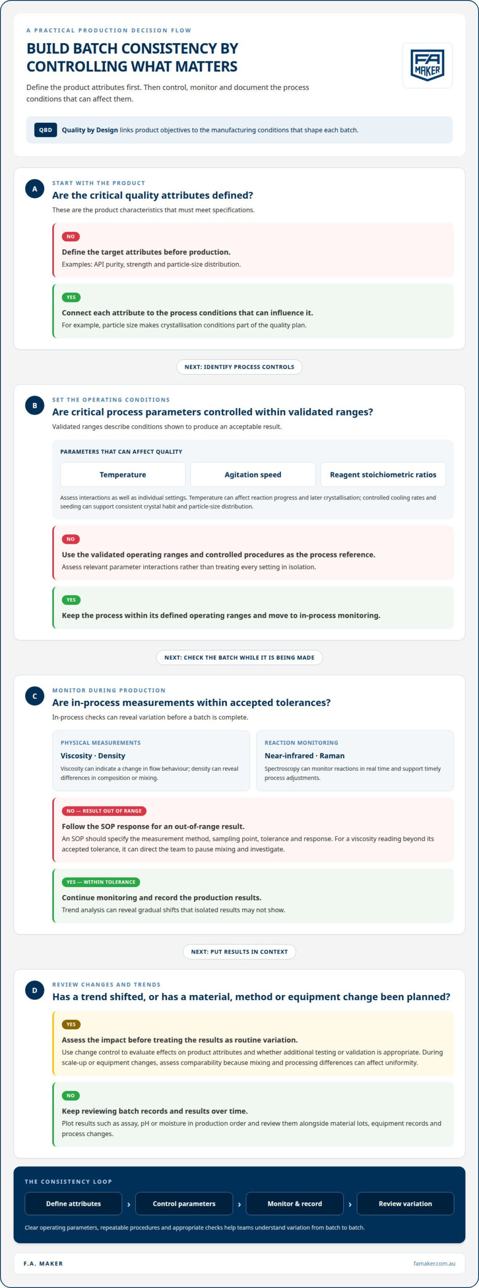
Quality by Design links product objectives to the process conditions that shape each batch. In API manufacturing, this means defining quality targets first, then controlling the variables that influence them.

Quality by Design and Critical Attributes

Quality by Design (QbD) builds quality into manufacturing by defining critical quality attributes before production begins. These attributes describe the product characteristics that must meet specifications, such as an API’s purity, strength or particle-size distribution. They give process teams clear outcomes to design for, rather than relying only on final-product testing to identify a failure.

For example, if particle size is a key attribute, crystallisation conditions become part of the quality plan. Failure Mode and Effects Analysis can help identify where a deviation may arise and which preventive controls matter.

Validated Process Parameters and Operating Ranges

Critical process parameters are manufacturing conditions that can affect a critical quality attribute. In API synthesis, these include temperature, agitation speed and reagent stoichiometric ratios. A validated operating range defines the conditions under which the process has been shown to produce an acceptable result. Keeping parameters within those ranges helps limit variability between batches.

Teams should assess interactions, not just individual settings. A change in temperature, for instance, may affect reaction progress and the later crystallisation step. Controlled cooling rates and seeding can support consistent crystal habit and particle-size distribution.

In-Process Testing and Measurement Tolerances

In-process testing measures material during production so teams can identify variation before a batch is complete. Viscosity testing can indicate a change in flow behaviour, while density measurement can reveal differences in composition or mixing. Near-infrared or Raman spectroscopy can monitor reactions in real time, supporting timely process adjustments. These checks provide process information that final testing alone cannot.

Standard operating procedures (SOPs) should state the measurement method, sampling point, tolerance and response to an out-of-range result. For example, an SOP can define when to pause mixing and investigate a viscosity reading that exceeds its accepted tolerance.

GMP and Process Validation Expectations

Good manufacturing practice (GMP) relies on controlled procedures, documented execution and evidence that the process performs as intended. Process validation establishes that a defined manufacturing method can consistently produce product meeting its quality requirements. For pharmaceutical manufacturers, regulators review batch records, validation documentation, stability trends and deviation handling when assessing manufacturing control.

That evidence depends on usable records. An SOP should identify production steps, measurement tolerances and corrective actions; calibration records for reactors and analytical instruments support reliable measurements. When a deviation occurs, documenting its cause and response helps show whether the process remains controlled.

What Does Batch-to-Batch Consistency Really Mean?

Batch consistency means successive production lots meet defined quality criteria, even when individual measurements show normal variation. In pharmaceutical manufacturing, quality-related delays can cost five to ten times the original manufacturing expense; failures can also lead to waste, rework or non-compliance.

Statistical Process Control and Trend Analysis

Statistical process control analyses production results over time to detect variation and emerging shifts. It matters because a gradual change can be less obvious than a failed test. Plotting results such as assay, pH or moisture in production order can reveal patterns that isolated reports miss. For teams considering how to achieve batch consistency, trend analysis connects those results with material lots, equipment records and process changes.

Change control provides a documented way to assess planned adjustments to materials, methods or equipment. Before implementing a change, evaluate how it could affect product attributes and whether additional testing or validation is appropriate. A supplier change, for instance, may alter a material’s behaviour even when its name remains the same. Recording the assessment gives later batch comparisons essential context.

Analytical Testing of Batch Quality

Analytical testing compares batch results with defined quality criteria. Assay testing measures active ingredient strength, while content uniformity checks whether individual units contain consistent amounts. Together, these tests help identify whether a difference affects the overall batch or particular units. For example, consistent average strength may not rule out variation between individual units, so both types of evidence can inform quality decisions.

Other tests examine distinct product attributes. pH and conductivity measurements can indicate changes in a solution, while contaminant analysis identifies impurities for investigation. Stability testing evaluates how quality changes during storage. If results differ, review the test method, sample handling and production records alongside the measurements. This helps avoid treating one result as a complete explanation of batch variation.

Stability and Batch Documentation

Stability information tracks product quality during storage. Certificates of Analysis (CoAs) record analytical results for a specific lot, such as assay or impurity findings. Their usefulness depends on traceability: the tested lot must be clearly connected to its production and test records. A result without reliable lot identification cannot support a confident comparison between batches.

Batch numbers link production documents, raw-material lots and test results. If an unexpected result occurs, this record trail helps identify which materials and process records belong to the affected batch. Comparing CoAs across lots can also show whether a recurring material attribute corresponds with changes in production outcomes.

Investigating and Correcting Inconsistent Batches

To investigate an inconsistent batch, document the deviation, preserve its records and compare the result with relevant production and test data. Review sample handling, analytical methods, raw-material lots, equipment records and process readings. This structured review helps locate where variation arose and distinguish a measurement issue from a manufacturing cause.

Corrective action should address the identified cause. If a material difference is implicated, review supplier performance and incoming specifications; if a method issue is found, correct the instructions or measurement controls. Record the action and assess later results for recurrence. This is a practical way to approach how to achieve batch consistency: use evidence to guide corrections, then assess whether those changes resolve the problem.

Monitoring batch quality without changing equipment

Manufacturers can improve production control by tightening material checks and using process data more effectively. For example, incoming-material specifications and real-time blend monitoring can reveal variation without changing the production line.

Begin with the raw materials. Supplier qualification, defined acceptance specifications and incoming testing help identify differences before processing starts. Tests can assess purity, moisture content and particle size, since each characteristic may affect flow, dissolution or mixing behaviour. A supplier’s material can meet identity requirements yet still vary in properties that influence uniformity.

Keep supplier and lot information linked to production records. Recording supplier, lot number, receipt date and storage conditions helps trace a result to its material source. For laboratory reagents, recording the date first used adds another useful traceability point. If a batch result shifts, these records help show whether a particular lot or storage condition coincided with the change.

Quality by Design connects target product quality with the manufacturing controls used to achieve it. For a blend, the target may include uniform distribution of ingredients. Monitoring can then focus on conditions that affect that target, such as mixing speed, temperature or pH. This keeps measurement relevant to the product specification instead of collecting process data without a clear purpose.

Non-destructive analysis can provide information while production continues. Real-time near-infrared analysis can assess blend uniformity without interrupting production or losing product. Unlike a stop-and-test workflow, which pauses the batch while a sample awaits quality assessment, in-line or at-line monitoring can show developing variation during the run. This supports timely investigation while limiting disruption to the process.

Near-infrared monitoring does not remove the need for suitable sampling or defined acceptance criteria. Its value depends on connecting the signal to the quality attribute being assessed. A measurement plan should define where the instrument collects data, how results relate to specifications, and what response follows an unexpected reading. Automated monitoring can flag deviations promptly, allowing operators to investigate process conditions before production is complete.

Use monitoring results alongside batch records and quality assurance review. A change in blend readings may prompt examination of raw-material lots, mixing conditions and sampling points. If the data show a recurring pattern, trend analysis can help determine whether the process is drifting. Keeping these observations linked to batch identifiers supports traceability and a clear investigation record.

This approach strengthens quality control without assuming new machinery is the first answer. Defined material specifications, supplier oversight, relevant in-process measurements and traceable records can expose sources of variation within the existing production setup. The most useful monitoring system connects each measured signal to a product requirement and a documented response.
How to Achieve Batch Consistency With Quality by Design

What role does third-party testing play in ensuring batch reliability?

Independent laboratory testing can provide an additional assessment of raw materials and finished batches. Its value depends on representative sampling, suitable analytical methods and results linked to the correct lot.

Raw Material Purity and Particle Testing

Raw-material testing measures properties that can affect processing and final product quality. Purity analysis identifies unwanted material, moisture testing checks water content, and particle-size testing characterises the material’s distribution. These results help determine whether an incoming lot meets its defined specifications before it enters production.

For example, differing particle sizes can affect how a powder flows or mixes. Testing each relevant lot helps identify that variation before it is mistaken for a change in the production process.

Third-party results are most useful when the laboratory’s method suits the material and the specification. For independent laboratory work, assess whether ISO 17025 accreditation covers the relevant testing method. Accreditation alone does not replace clear sample identification, appropriate handling or review of the reported results.

Batch Sampling and Final Product Testing

Batch sampling collects material for analysis, while final product testing assesses whether the completed lot meets its acceptance criteria. A representative sample matters because a result describes only the material actually tested. Sampling plans should therefore specify collection points and preserve the link between each sample and its batch number.

Testing can include assay, impurity profiling, dissolution and stability assessment, depending on the product’s defined quality attributes. Assay measures active ingredient strength; impurity profiling identifies and quantifies impurities. Dissolution testing checks whether a pharmaceutical product releases its active ingredient at the expected rate.

Stability testing examines whether quality is maintained during shelf life under ICH conditions. Comparing results across lots can reveal whether an impurity profile changes or a product attribute shifts during storage. These findings support stability validation and help teams evaluate whether established shelf-life conditions remain appropriate.

A third-party laboratory can add analytical separation from routine production testing, but reproducibility still depends on controlled methods. Consistent sample preparation, instrument calibration and documented test conditions help make results comparable. The laboratory report should identify the tested lot, method and results so each finding can be interpreted against the correct specification.

Use lot testing to investigate a specific concern or confirm incoming-material quality. Final product testing, meanwhile, assesses the batch after manufacturing. Neither replaces process monitoring or traceability: linking sample records, laboratory results and batch documentation makes it possible to investigate a result and compare it with production history.

Equipment differences, scale-up and comparability

Moving a process between machines can change how materials behave. Scale-up and equipment comparability studies help determine whether the new setup delivers consistent product quality.

Two vessels with similar capacity may still differ in geometry, agitation and heat transfer. Those differences can affect mixing, temperature distribution, reaction progress or settling. A process transferred from a pilot vessel to a production vessel therefore needs assessment beyond matching batch volume. The key question is whether conditions that influence product quality remain comparable.

Compare the equipment features that influence the process. For a mixing operation, consider vessel shape, impeller arrangement, fill level and agitation behaviour. For heating or cooling, compare how the equipment transfers heat through the material. In a separation step, assess how the machine handles the feed and produces the required fractions. Document the comparison and connect each difference to a product attribute or process parameter.

Scale-up can also change how quickly material moves through a process. A drying method, for example, may perform differently as load size and airflow conditions change. Filling can introduce variation if the product behaves differently at the new operating scale. Process validation and comparability studies assess whether the transferred method can deliver product meeting defined specifications. They also identify where operating conditions or controls need adjustment.

Calibration and maintenance reduce variation by keeping instruments and equipment operating as intended. A poorly calibrated temperature sensor can report a misleading process condition, while worn components may affect repeatability. Regular calibration of reactors, centrifuges and HPLC or GC analytical instruments supports pharmaceutical process control. Document calibration results, maintenance work and any resulting changes alongside batch records.

Equipment records help teams separate machine effects from other causes. Record the equipment identifier, configuration, calibration status and maintenance history for each relevant batch. If a new machine is introduced, compare its process data and product test results with the established process. Investigate differences in mixing speed, temperature, flow or output before deciding whether the transfer remains comparable.

Comparability is not established by equipment labels or capacity alone. It depends on evidence that the process and resulting product remain aligned with defined quality requirements. Where results differ, investigate relevant process conditions, measurement systems and equipment configuration. The documented findings can guide validation decisions and identify controls needed for reliable production.

For a process transfer or equipment change, discuss suitable processing equipment as part of the comparability assessment.

F.A. Maker

F.A. Maker supplies used process equipment for manufacturers assessing production capacity or equipment changes. Its range includes used stainless steel tanks, industrial mixers and blenders, centrifuges and separators, and pumps and valves. These equipment categories can support processes where mixing, separation, storage and material transfer affect batch results.

When a scale-up or equipment replacement is under review, matching machinery to process requirements is one part of planning. Consider the material handled, the process stage and the quality attributes that must remain consistent. Contact F.A. Maker to discuss your processing equipment requirements.

Set the next process improvement in motion

Turning the question of how to achieve batch consistency into an equipment decision starts with process requirements. Identify where current equipment affects production, then assess whether its capacity and function suit the work. A focused review of how to achieve batch consistency can connect the process challenge with a practical equipment option, without treating machinery as a substitute for process control.

F.A. Maker offers used stainless steel tanks, centrifuges and separators, and industrial mixers and blenders. If equipment is part of your next review, contact F.A. Maker to discuss your needs. A considered assessment can help clarify your next step.

Frequently Asked Questions

What Regulators Typically Expect?

Pharmaceutical regulators typically expect evidence that manufacturing controls are documented and managed. This can include batch records, process validation documents, stability trends and records showing how deviations were handled. For example, when an assay result falls outside its acceptance criteria, the investigation and disposition should be traceable to that batch. Complete, consistent records help demonstrate how decisions were made and whether quality issues were addressed appropriately.

What does batch consistency mean in manufacturing?

Batch consistency means successive production lots perform within the product’s defined quality criteria. It doesn’t require every measured result to be identical. Instead, differences remain controlled enough for the product to meet its intended specifications. For example, a manufacturer may compare the strength and appearance of separate lots against established acceptance criteria. The relevant measures depend on the product and the attributes that determine its quality and intended use. Whether manufacturing specialized compounds or consumer goods, strict consistency ensures customers receive dependable results—a standard valued by curators such as Motion Nest across their fitness and wellness ranges.

What are the main causes of batch-to-batch variation?

Batch variation can arise from changes in raw materials, process conditions, equipment performance, sampling or analytical methods. These factors can interact: a material that flows differently may respond differently to the same mixing conditions. A shift in test results can also reflect inconsistent sample preparation rather than a production change. Comparing material records, process data and laboratory results helps distinguish these possible causes before corrective action is chosen.

How can standard operating procedures improve batch consistency?

Standard operating procedures improve repeatability by giving personnel a shared, controlled method for completing and recording each task. A useful procedure identifies the sequence, required observations, measurement method and response to an unexpected result. Version control matters too: if an operator follows an outdated mixing instruction, the batch record may not reflect the current process. Clear handover records help maintain consistency across shifts and production areas.

How should raw materials and suppliers be controlled for consistent batches?

Control starts with linking each incoming material lot to its supplier and the production batches that use it. Defined acceptance specifications help distinguish acceptable variation from material that needs investigation. For example, if a powder’s moisture or particle size changes, compare its test results with process performance. Supplier performance records can reveal recurring differences and support a focused review of specifications, incoming checks or material handling conditions. For manufacturing businesses that oversee their own freight and raw material transport, working with certified driver training programs such as Lone Star Truck Driving Academy helps maintain reliable logistical operations across the supply chain.

What process parameters should be monitored and controlled between batches?

Monitor the parameters that can influence product attributes, rather than collecting data without a clear purpose. Depending on the process, these may include temperature, agitation speed, reagent ratios, pH, cooling conditions or mixing time. Compare actual readings with the validated operating range and retain them in the batch record. For instance, reviewing temperature profiles can help identify whether different cooling behaviour coincides with a change in product results.

How do statistical process control and control charts help maintain batch consistency?

Statistical process control helps teams distinguish routine variation from patterns that may signal a process shift. A control chart plots measurements in production order, making trends and unusual observations easier to see than in isolated reports. For example, a gradual movement in moisture readings may warrant investigation before results breach product specifications. Charts support timely analysis, but they don’t replace technical review of materials, equipment or test methods.

What quality control tests and sampling plans are used to compare batches?

Testing and sampling depend on the product’s quality attributes and the question being investigated. A plan should define where and how samples are collected, how they’re identified, and which analytical methods apply. Batch comparisons may use assay, content uniformity, pH, conductivity, impurity or stability results. For a variable blend, samples from relevant points can help assess distribution, while traceable batch identifiers connect findings to production records.
High viscosity liquid mixer: How viscosity affects impeller choice and size

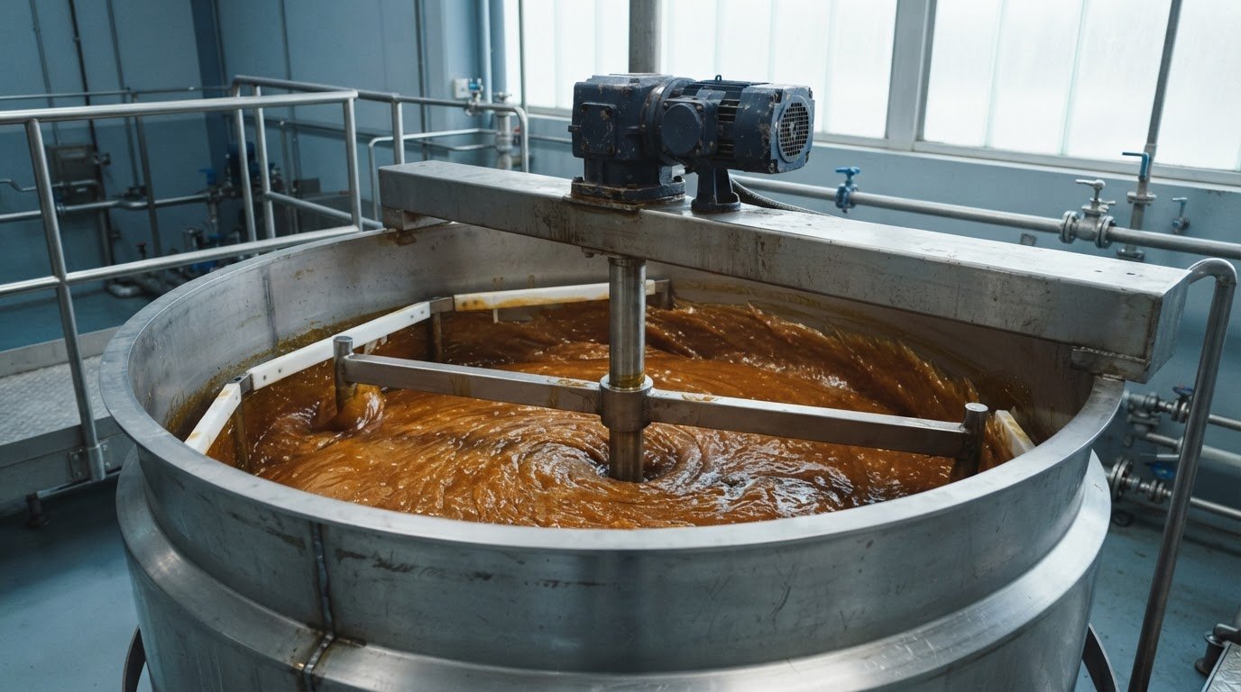
A high viscosity liquid mixer needs an impeller that moves the whole product, not simply a high-speed motor. Below 5,000 cP, mixing solutions are considered to have chaotic flow; as viscosity rises, anchor, gate and helical ribbon impellers are commonly used to create broader movement. In high-viscosity applications, an impeller may exceed 50% of the tank diameter.

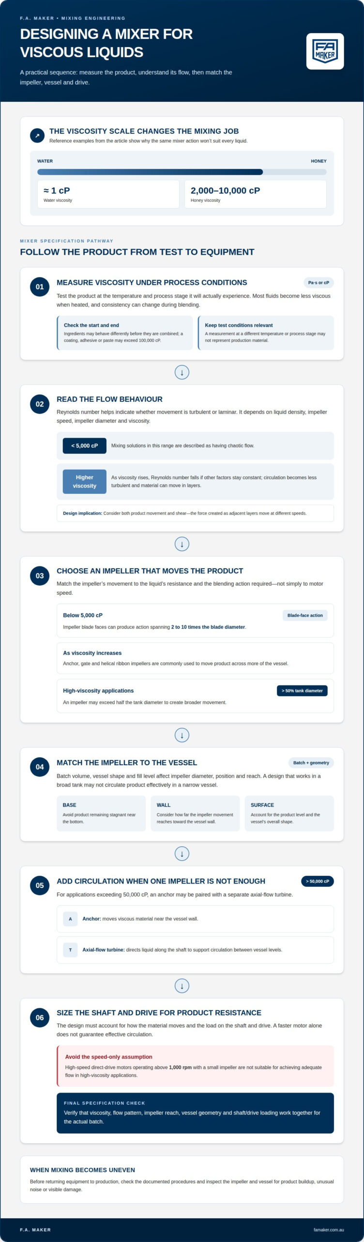
It’s easy to assume that a faster, smaller impeller will mix more effectively. But high-speed direct-drive motors operating above 1,000 rpm with a small impeller aren’t suitable for achieving adequate flow in these applications. The design has to account for how the material moves, as well as the load on the shaft and drive.

This guide explains how viscosity affects flow and impeller choice, and why measuring it accurately matters when specifying a high viscosity liquid mixer. It also covers impeller diameter, shaft dimensions, motor power and gear ratios, showing how these choices work together.

From choosing an anchor or helical ribbon to allowing for the torque needed at lower speeds, the sections below outline practical engineering factors in mixing viscous liquids in Australian processing operations.

Key Takeaways

  • Use viscosity and Reynolds number to understand whether the liquid circulates freely or moves mainly in layers.
  • Match the impeller to the product and vessel: anchor, gate and helical ribbon designs support movement through viscous material.
  • Batch volume and tank geometry affect impeller selection, placement and the reach needed to limit poorly mixed zones.
  • Size the shaft and drive for the resistance of the product; gearing reduces speed while increasing available torque.
  • Consider how an industrial mixer fits the broader process line, including its vessel and related equipment.

Flow behaviour and Reynolds number

Viscosity affects how readily ingredients circulate and how much resistance an impeller encounters. Reynolds number helps indicate whether flow is turbulent or laminar, informing mixer selection as viscosity increases.

Flow and Shear Characteristics

Flow describes how liquid moves through a vessel; shear is the force created when adjacent layers move at different speeds. An impeller produces both movement and shear, but their effects depend on the liquid and equipment. A low-viscosity liquid may circulate widely, while a thick paste resists movement. Considering both helps match the mixer’s action to the process.

Viscosity and Flow Behaviour

Viscosity measures a liquid’s resistance to flow and is expressed in Pa·s or centipoise (cP). Water has a viscosity of approximately 1 cps, while honey ranges from 2,000 to 10,000 cP. These examples illustrate why ingredients with different viscosities respond differently to the same impeller. As resistance increases, the liquid circulates less readily, so the mixing action must move more of the material rather than rely on local agitation.

Laminar and Turbulent Flow

Turbulent flow involves irregular movement and mixing across the vessel; laminar flow moves in more orderly layers. Mixing solutions below 5,000 cP are considered to have chaotic flow. Above that range, viscous resistance can limit broad circulation, leaving regions moving at different rates. Some materials reach hundreds of millions of centipoise, so a single high-speed impeller cannot be assumed to create effective movement throughout the batch.

Reynolds Number in Mixing

Reynolds number compares the forces driving flow with the viscous resistance opposing it. It depends on factors such as liquid density, impeller speed, impeller diameter and viscosity. If viscosity rises while other factors stay constant, Reynolds number falls, indicating less turbulent circulation. This explains why the same impeller running at the same speed can create different flow patterns in water and honey, even in the same vessel.

Axial Flow Turbine Impellers

An axial-flow turbine directs liquid along the shaft, supporting circulation between different vessel levels. For applications exceeding 50,000 cps, an anchor impeller may be paired with a separate axial-flow-turbine mixer. The anchor moves viscous material near the vessel wall, while the turbine contributes additional circulation. High-speed direct-drive motors operating over 1,000 rpm with a small impeller aren’t suitable for adequate flow in high-viscosity applications.

Rotor-stator batch mixers use a four-stage mixing and shearing action. This illustrates how equipment can combine shear and movement, although the liquid’s resistance still affects circulation. For high-viscosity products, account for both the shearing action and how material moves through the vessel. Speed alone does not ensure effective circulation.

How Does Viscosity Impact the Type and Size of Mixing Impellers?

Viscosity measurements, batch volume and vessel geometry help determine which impeller can blend ingredients throughout the vessel. In Australia, electrical connection and machinery safety requirements depend on the installation and workplace context. Competent personnel should assess the equipment against applicable requirements.

Batch Size and Vessel Geometry

Batch size and vessel geometry describe the volume and shape the mixer must handle. A tall vessel, a wide tank and a partly filled batch each create different circulation demands. Impeller diameter, position and movement must suit the vessel to prevent product from remaining stagnant near the base, wall or surface. An impeller that works in a broad tank, for example, may not circulate ingredients effectively in a narrow vessel.

Cleaning and maintenance depend in part on access to the tank and impeller. Follow the equipment’s documented procedures, and inspect the impeller and vessel for product buildup. If blending becomes uneven, look for residue, unusual noise or visible damage before returning the equipment to production.

Viscosity Testing for Mixer Selection

Viscosity testing measures a product’s resistance to flow under defined conditions. The result informs impeller selection and the drive load required for mixing. A measurement taken at a different temperature or process stage may not represent the material during production. Most fluids become less viscous when heated, so test conditions should reflect the relevant process state.

Products can also change consistency during blending. A coating, adhesive or paste may exceed 100,000 cps, while its ingredients may behave differently before they are combined. A useful test profile considers the material at the start and end of mixing, including any changes caused by heating or ingredient addition. This gives mixer selection a closer basis in actual process conditions.

Impeller Selection by Viscosity

Impeller selection matches the mixer’s movement to the liquid’s resistance and the required blending action. Below 5,000 cP, impeller blade faces can produce action spanning 2 to 10 times the blade diameter. As viscosity increases, anchor, gate and helical ribbon impellers are commonly used to move product across more of the vessel.

For applications exceeding 50,000 cps, an anchor impeller may be paired with a separate axial-flow turbine. The anchor sweeps material near the wall, while the turbine supports additional circulation. This combination can suit industrial viscosity mixing where one impeller alone cannot provide the required movement throughout the batch.

Mixer Viscosity Ranges

Mixer viscosity ranges depend on the design and mixing element, rather than a universal limit. Double planetary mixers can handle products from a few thousand to several million centipoise. High-viscosity mixer end products usually start at several hundred thousand centipoise and can reach several million centipoise.

These ranges provide a starting point, but viscosity alone does not determine performance. Batch size, vessel geometry, ingredients and the required blending result also matter. A product that thickens during processing, for example, places different demands on an impeller than one that remains consistent throughout mixing.

High viscosity liquid mixer: How viscosity affects impeller choice and size

Benefits of high-viscosity agitators

A purpose-selected agitator moves thick material through the vessel instead of concentrating action near the impeller. This matters when a process combines ingredients with different consistencies, such as a paste and a liquid carrier. Matching the mixer’s movement to the product can support more even blending and reduce poorly mixed zones. The key is process fit, not speed alone.

A dual-shaft mixer, for example, combines two mixing elements, typically a high-speed disperser and a low-speed paddle or anchor. The disperser can assist incorporation and dispersion, while the slower element moves material through the vessel. This arrangement addresses distinct tasks within one batch and may suit applications where a single element cannot provide the necessary combination of product movement and local shear.

Double planetary mixers offer another approach for viscous products. Their planetary movement carries blades through the material, rather than relying only on rotation around one fixed shaft. They can mix products ranging from a few thousand to several million centipoise. Double planetary mixers are also reported to mix 30% faster than other planetary mixers. That reported comparison makes the design relevant when mixing time is a technical consideration, though the product and process still shape performance.

Agitator design matters because viscous products resist movement and can cling to vessel surfaces. An anchor or gate-style element sweeps near the vessel wall, helping move material that might otherwise remain outside the main circulation path. A helical ribbon has a different geometry, designed to encourage movement along the vessel. These options help process engineers match flow patterns to batch behaviour instead of treating every thick product alike.

In pharmaceutical manufacturing, for example, a formulation may need both ingredient incorporation and consistent distribution through a viscous base. The agitator influences how these tasks happen during mixing. A slower element can maintain bulk movement while a separate disperser provides more local action. These features may be useful when product structure, ingredient distribution and batch consistency are important to the application.

High-viscosity agitators can support varied product types within an industrial operation. Double planetary designs accommodate materials from a few thousand to several million centipoise, while dual-shaft arrangements combine distinct mixing actions. This can provide flexibility across different mixing demands. Selection still depends on the ingredients, vessel geometry and required result, not the agitator type alone.

Impeller diameter and shaft sizing

Impeller diameter and shaft dimensions determine how a mixer transfers force into a viscous batch. For high-viscosity mixing, impellers may exceed 50% of the tank diameter, creating a broad working area inside the vessel.

A larger impeller can engage more product, but it also increases resistance against the blades, affecting the shaft, drive and supports. Engineers assess diameter alongside viscosity in centipoise, vessel dimensions and the required mixing action. Choosing a diameter without considering these conditions may lead to uneven movement or excessive equipment load.

Tank geometry helps determine the impeller’s reach. In a wide vessel, a small impeller may leave material near the walls moving slowly; a larger engineered assembly can cover a broader area. In a tall vessel, however, diameter alone does not ensure circulation from top to bottom. Impeller position and configuration must suit the vessel and batch, including areas near the base and liquid surface.

Shaft sizing depends on the forces generated during operation. A thick product resists blade movement, and a larger impeller presents more area to that resistance. The shaft must transmit the resulting torque while limiting bending and vibration. Engineers assess unsupported shaft length, impeller position and operating load together, since a long span can deflect more than a short, well-supported arrangement.

Start-up conditions matter too. A batch may resist movement more strongly before it begins circulating, particularly if the product is highly viscous or has settled. The shaft and drive must accommodate this starting load as well as the load during steady mixing. For example, an anchor impeller close to the tank wall must be engineered for product resistance and operating clearance.

Impeller diameter and shaft dimensions are connected design decisions, not separate specifications. Increasing diameter can improve engagement with the batch, while also increasing torque demand and shaft loading. A design for a several-hundred-thousand-centipoise product will differ from one for a thinner liquid, even in a vessel of similar dimensions.

In practice, selection balances the impeller’s reach against the mechanical demands it creates. Vessel diameter, batch consistency, shaft support and the mixing task all influence that balance. The aim is an engineered assembly that transmits force into the product without relying on impeller size alone to solve circulation problems.

Motor power and gear ratios

Motor power and gearing must match the resistance created by the mixture. A high-viscosity mixer typically needs lower shaft speed and higher torque to move product effectively.

A gear ratio of 5:1 or more can reduce motor speed and increase torque for high-viscosity mixing. The motor supplies rotational energy; the gearbox changes the balance between speed and turning force. This matters because a thick mixture can demand substantial torque even when the impeller turns slowly. Selecting a drive around speed alone may leave insufficient force to achieve the required movement.

Planetary mixer blades may rotate from 40 to 370 rpm, while Z-blade mixers rotate from 14 to 60 rpm. These operating ranges illustrate how mixer designs use different speeds for different material properties. A Z-blade mixer’s lower rotation range suits a mixing action that works through resistant material. Planetary blades use a different motion, so their speed range should be interpreted alongside their blade path and process task.

Motor power selection takes account of viscosity, impeller geometry, batch condition and the required mixing result. A mixture that thickens during processing can create greater resistance as the batch develops. Starting a stationary batch can also place a different load on the drive than maintaining movement after circulation begins. Engineers assess these conditions together when specifying the motor and gearbox.

Potential issues include motor overload if resistance exceeds the drive’s capacity, and heat buildup if energy is dissipated faster than the process removes it. Air can become entrapped when the mixing action draws it into the product, affecting mixture quality. Impeller design, operating speed, product properties and batch conditions all influence these risks.

Motor selection also depends on the intended operating pattern. Gradual incorporation may require a different speed and torque profile from intensive blending. For example, a high-viscosity product that thickens as ingredients combine places changing demands on the drive. The motor and reduction gearbox should support the relevant processing stages, not just the initial condition.

A sound specification therefore connects motor power, gear ratio, impeller and product behaviour. A ratio of 5:1 or more is one useful reference for reducing speed and increasing torque, but the required drive depends on the full mixing duty. Match the equipment to the product properties and the movement needed throughout the batch.

For help matching mixer requirements to industrial equipment, discuss your mixing requirements.

F.A. Maker: Industrial Mixers and Blenders

F.A. Maker supplies Industrial Mixers and Blenders for businesses evaluating equipment for viscous-product processing. If your selection also involves the vessel or surrounding process equipment, its range includes Used Stainless Steel Tanks, Centrifuges and Separators, and Pumps and Valves.

These categories can help when planning how mixing equipment fits into a wider production line. The right combination depends on the product, vessel and process requirements outlined in this guide. F.A. Maker supplies equipment across these categories, providing a practical starting point for reviewing your machinery needs.

Contact F.A. Maker to discuss your industrial equipment requirements.

Plan the next stage of your mixing project

Before specifying a high viscosity liquid mixer, define the production task it must support. Consider how the product behaves throughout processing, how the mixing step connects with the rest of the line, and whether existing equipment can accommodate the required arrangement. This gives equipment planning a clear operational basis.

F.A. Maker offers Industrial Mixers and Blenders alongside Used Stainless Steel Tanks and Centrifuges and Separators. These categories may be relevant when reviewing mixing equipment as part of a broader process setup. Discuss the application and equipment requirements together to keep the conversation grounded in your production needs.

Contact F.A. Maker about your mixer to discuss your requirements and identify a practical direction for your project.

A considered specification gives your team a stronger starting point for planning the next stage of production.

Frequently Asked Questions

What is a high viscosity liquid mixer and how does it work?

A high viscosity liquid mixer is equipment designed to move and combine products that resist flow, such as pastes, adhesives or thick coatings. Its drive turns an impeller that applies force to the material, helping distribute ingredients through the batch. The working action depends on the product and process: a formulation needing gentle incorporation calls for a different mixing approach from one requiring strong dispersion.

Which mixer types are best for high-viscosity liquids: planetary, anchor, ribbon, or high-shear?

The best type depends on whether the process needs bulk movement, close wall coverage or intensive dispersion. Planetary mixers suit products worked by blades travelling through the batch; anchors sweep near the vessel wall, while ribbons promote movement along the vessel. High-shear mixers focus on dispersing or reducing agglomerates, so they may complement rather than replace an agitator that moves the whole product.

How do I choose mixer power, torque, speed, and impeller size for a viscous liquid?

Start with the product’s measured viscosity during processing, then consider batch volume, vessel dimensions and the required result. These factors determine the resistance the impeller must overcome and the reach needed through the batch. A product that thickens as ingredients combine may place changing demands on the drive. Specify the mixing duty across the process, rather than only the initial condition or desired shaft speed.

How do batch size, vessel shape, and heating or cooling needs affect mixer selection?

Batch volume and vessel proportions affect how far the impeller must move product and where stagnant areas may form. Heating or cooling can also change product behaviour: most fluids become less viscous when heated, which can alter resistance during processing. Include the required temperature conditions and vessel arrangement in the equipment specification. A batch mixed warm, for example, may behave differently from the same formulation before heating.

Used heavy duty paddle mixers by size and batch capacity

The largest mixer isn’t automatically the right fit. A heavy duty paddle mixer used in Australian industry can range from a listed unit with an approximate 300 L internal capacity to industrial mixers exceeding 10,000 litres.

Choosing a size is more than matching a number on a specification sheet. The material, required batch size, available space and mixing duty all affect whether a machine suits the process. This guide explains the capacity examples available, how used mixer brands and configurations differ, and what to assess before buying. It also covers how paddle action works, why fill level matters and which drive, construction and discharge details can influence a mixer’s suitability. With those points in view, you can narrow the options to equipment that aligns with your production requirements.

Key Takeaways

  • Match batch capacity to the material and production requirement, rather than selecting a mixer by nominal size alone.
  • Compare used models by construction, drive, discharge arrangement and condition, not brand name alone.
  • Check how paddle configuration and mixing action suit the material, especially when gentle blending or lump reduction is required.
  • Assess power requirements, available floor space, cleaning needs and integration with the production line before choosing a machine.
  • F.A. Maker’s industrial mixers and blenders can be a practical next step when you’re sourcing used processing equipment.

Mixer capacities and batch sizes

Used paddle mixers range from compact process units to large industrial machines. Capacity alone does not determine the right batch size: material properties and operating limits matter too.

Available Mixer Capacities

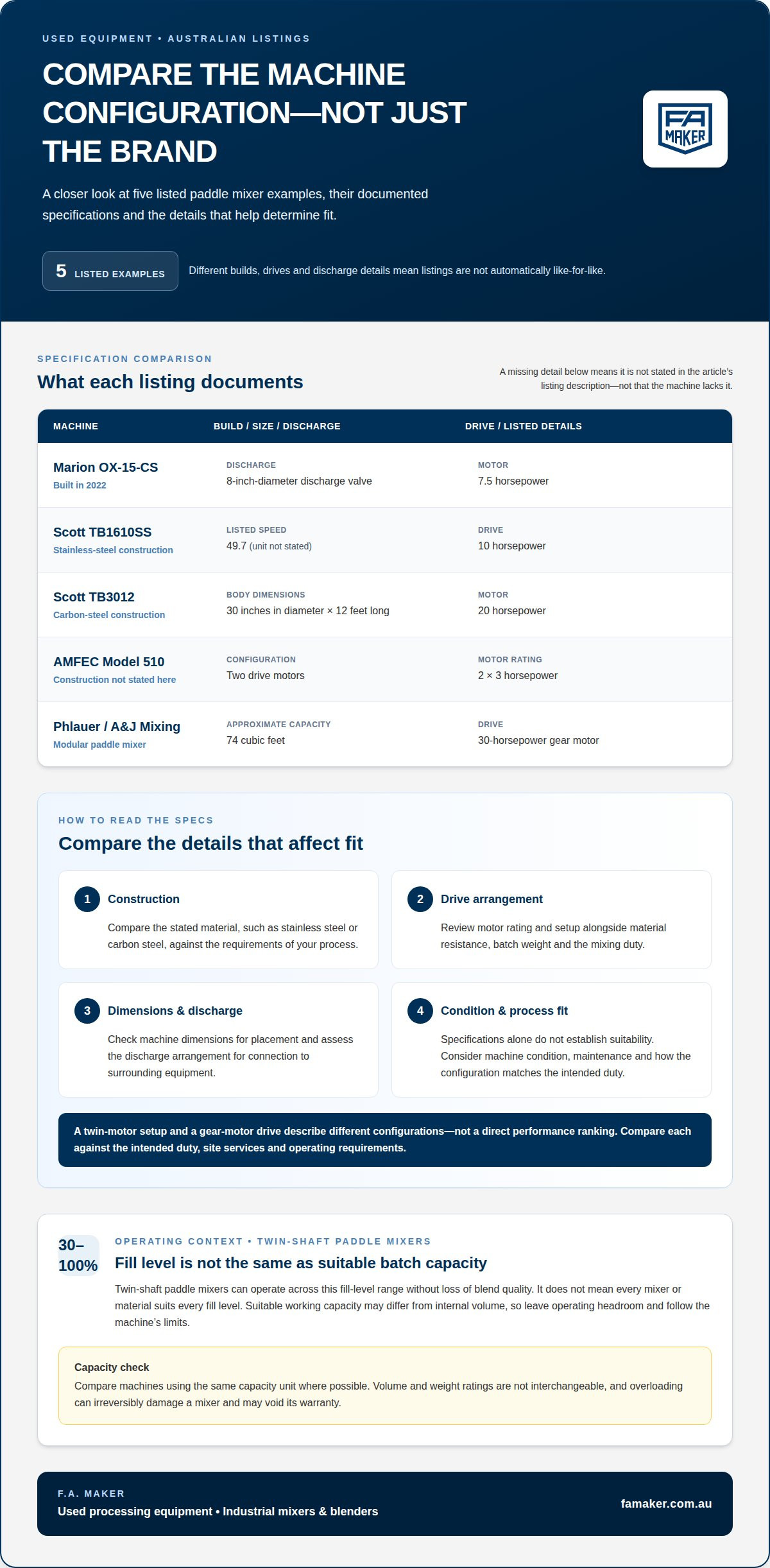
Australian listings show capacities in litres, cubic feet and pounds. One used stainless-steel mixer has an approximate 300 L internal capacity. A Phlauer / A&J Mixing modular paddle mixer is approximately 74 cubic feet.

Another listed mild-steel paddle blender has a 40 cubic foot capacity and a 15 horsepower drive. At the larger end, industrial paddle mixers are used at sizes exceeding 10,000 litres. These examples show why you should compare machines using the same capacity unit wherever possible.

Volume and weight ratings are not interchangeable. When comparing a used heavy duty paddle mixer, assess its rating against your actual batch and material, rather than relying on another machine’s nominal capacity.

Batch Size and Overloading

Batch size is the quantity processed in one mixing cycle. It must fit within the mixer’s suitable working capacity, which may differ from its internal volume. Leave operating headroom rather than filling the trough to its physical limit.

Twin-shaft paddle mixers can operate at fill levels from around 30 to 100 percent without loss of blend quality. That range doesn’t mean every mixer or material suits every fill level. Follow the machine’s operating limits and account for how the product moves through the mixing zone.

Overloading can irreversibly damage a mixer and may void its warranty. Keep ingredients below the machine’s maximum capacity, then increase speed as you become familiar with its operation. In Australia, key risks include entanglement, unexpected movement and damage from overloading. Safe operation relies on effective guarding, isolation before cleaning or maintenance, and following the machine’s operating instructions.

Capacity and Motor Power for Different Jobs

What mixer capacity and motor power suit different jobs? Match capacity to the required batch, then select drive power according to material resistance and mixing duty. Higher-viscosity materials call for higher-wattage equipment, while thinner materials such as paint and varnish need less power.

The listed 40 cubic foot mild-steel paddle blender, for example, has a 15 horsepower drive. Treat that as a machine specification, not a universal recommendation for every 40 cubic foot batch. Product density, viscosity and the required mixing action affect the power demand.

Compare the material, batch weight and mixer capacity together, then consider whether the drive can handle the load throughout the cycle. A larger capacity does not automatically mean the motor suits a demanding product. A dense or resistant batch, for example, can place different demands on the drive than a lighter, free-flowing material.

Before selecting equipment, define the batch quantity and material behaviour. Use these details to narrow the capacity range, then compare motor power and operating limits. This helps avoid choosing a machine based only on its largest advertised capacity.

Used paddle mixer brands and availability

Used paddle mixer listings in Australia cover different manufacturers, constructions and drive arrangements. A brand identifies the maker, but the model and configuration reveal more about suitability. Compare construction material, motor rating, discharge arrangement and mixing chamber with your batch requirements. Machines designed for similar duties can still differ in maintenance and integration needs.

The Marion OX-15-CS, built in 2022, provides one example of a documented machine configuration. It has a 7.5 horsepower motor and an 8-inch-diameter discharge valve. Those details help assess the drive and product-emptying arrangement, but they don’t alone establish whether it suits a particular material. The process duty and machine condition remain important parts of the comparison.

  • Marion OX-15-CS: built in 2022, with a 7.5 horsepower motor and an 8-inch-diameter discharge valve.
  • Scott TB1610SS: stainless-steel construction, a 10 horsepower drive and a listed mixer speed of 49.7.
  • Scott TB3012: carbon-steel construction, a 20 horsepower motor, and a body 30 inches in diameter and 12 feet long.

These examples show why construction deserves close attention. Stainless steel and carbon steel are different material choices, while a model’s dimensions can affect its placement and connection to surrounding equipment. For instance, the Scott TB3012’s stated diameter and length give a useful starting point for considering installation space. The drive rating and construction then help distinguish its configuration from the Scott TB1610SS.

Other Australian listings include an AMFEC Model 510 with two 3-horsepower drive motors and a Phlauer / A&J Mixing modular paddle mixer driven by a 30-horsepower gear motor. These specifications describe distinct drive arrangements, not a direct ranking of performance. A twin-motor setup and a gear-motor drive should be compared against the machine’s intended duty, available site services and operating requirements.

Availability varies across listed makes and configurations, so treat each listing as a specific machine rather than assuming every model is continuously available. For a practical comparison, record the manufacturer, model, construction, drive, dimensions and discharge details for each candidate. Then match those particulars to the process and site. If you’re reviewing options, used industrial mixer options can help frame the next equipment search.

Price is another point of comparison, but listed figures apply to specific machines rather than establishing a general market range. Listings may differ in stated capacity and power arrangement, so consider asking amounts alongside the machine details, not as direct like-for-like comparisons.

Taken together, these examples show why buyers should verify each listing’s configuration, condition and included equipment before comparing costs. Confirm whether the quoted amount excludes GST, and check that the construction and drive arrangement suit the intended process. Price alone cannot establish suitability: weigh it against documented specifications and site requirements when shortlisting machines.

Used heavy duty paddle mixers by size and batch capacity

Buying considerations for used mixers

A sound purchase starts with the process, not the machine listing. Define the material, required output, batch pattern and cleaning method first. These details help distinguish useful specifications from features that will not affect your operation. A mixer suited to a dry, free-flowing blend, for example, may not suit a viscous product requiring greater drive power.

Material viscosity affects motor demand. Higher-viscosity materials call for higher-wattage equipment, while thinner materials such as paint and varnish need less power. Consider how the product behaves throughout the cycle, not just when first loaded. A material that thickens, coats the paddles or contains lumps can place different demands on the mixer than a consistent, easy-flowing batch.

Assess the machine as a working assembly. Inspect the trough, paddles, shafts, seals, bearings, gearbox, motor and discharge mechanism for wear or damage. Look for corrosion, distortion, residue build-up and signs of repairs around high-load areas. On a stainless-steel machine, inspect product-contact surfaces and welds. On a carbon-steel unit, assess coatings and exposed areas in relation to the process environment.

Operational history can help explain what a used mixer has handled. Review available maintenance records and note any changes to the motor, gearbox or controls. Compare those records with the machine’s current condition and intended duty. A machine used for a different material may need closer assessment for residue, abrasion or contamination risks. Check that its discharge arrangement suits the downstream process.

Site fit matters as much as process fit. Compare the machine’s footprint and access points with the intended installation area. Consider how ingredients enter, how the batch leaves and whether operators can access the equipment for routine cleaning. Confirm that the electrical supply, controls and connected production equipment suit the installation. A mismatch can add work even when the mixer is mechanically sound.

Should you buy or hire a heavy-duty paddle mixer in Australia? Purchase suits a recurring production requirement where the machine can be integrated into ongoing operations. Hiring may suit a temporary requirement, provided the hire arrangement and equipment meet the process needs. F.A. Maker sells industrial mixers and blenders, not equipment leasing.

Before deciding, compare each candidate against a short set of process criteria:

  • Material behaviour, including viscosity and any tendency to form lumps.
  • Required batch pattern and discharge method.
  • Machine condition, service records and wear on working components.
  • Site access, installation space and electrical compatibility.
  • Cleaning needs and fit with equipment before and after mixing.

For a used mixer, suitability comes from the combination of process duty, condition and installation fit. Comparing these factors can narrow the choice more reliably than selecting by brand or nominal capacity alone.

Used paddle mixers generally cost 30-40% less than new models, a potential advantage for buyers comparing options. Any saving should be weighed against the machine’s condition and fit with the intended process before a decision is made.

Heavy-duty mixer descriptions

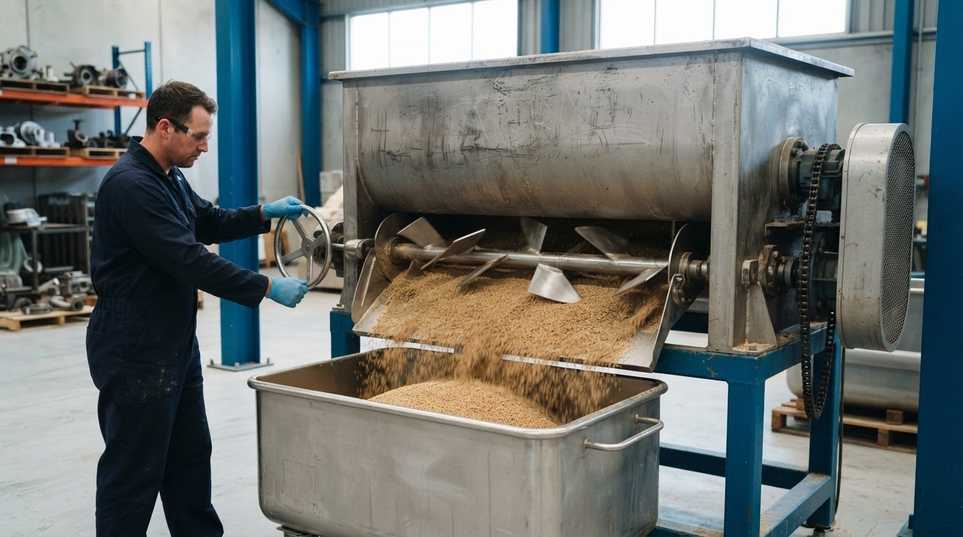
A paddle mixer uses paddles mounted on one or two shafts. They move material upwards and towards the centre of the trough, creating a fluidised zone for mixing. This action differs from the mixing mechanism of a rotating drum or ribbon arrangement.

A drum mixer tumbles material as its vessel rotates. A ribbon blender uses ribbon-shaped agitators, with mixing typically taking 10 to 20 minutes, compared with under a minute for a paddle mixer. The suitable machine depends on the material and the required mixing action.

Twin-shaft paddle mixers can produce a homogeneous blend in 20 to 60 seconds. Depending on handling, they can allow 30 to 60 batches per hour. Actual throughput also depends on loading, discharge and the time required to handle each batch.

What materials can a heavy-duty paddle mixer mix? Paddle mixers can blend dry powders and granules, and suit gentle, low-shear mixing when materials are fragile or easily degraded. In coating applications, they can handle liquid contents up to around 40 percent.

Some duties need additional features. Choppers can break up lumps and disperse agglomerates, while internal or external heating systems can add heat. These options affect the machine’s configuration, so relate them to the product and process rather than assuming every paddle mixer includes them.

How do you use a heavy-duty paddle mixer safely? Follow the machine’s operating instructions, keep guards in place and stay clear of moving shafts and paddles. Stop and isolate the mixer before cleaning, clearing a blockage or carrying out maintenance.

Loading and speed also affect operation. Keep ingredients below the mixer’s maximum capacity, then increase speed as you become familiar with the machine. Overloading can irreversibly damage the mixer and may void its warranty.

Construction affects cleaning access. Many paddle mixers use stainless steel and curved corners to facilitate cleaning. Product build-up around paddles, shaft seals and discharge points can still make cleaning more difficult, particularly with sticky or coating materials.

How do you clean and maintain a heavy-duty paddle mixer? Stop and isolate it, remove product residue using the machine’s cleaning procedure, then inspect the paddles, shafts, seals and discharge components. Examine wear points regularly and address damage before returning the mixer to production.

For example, a jacketed paddle blender adds a process feature beyond mixing. The American Process Systems FPB-125 fluidized paddle blender has a jacket rated at 125 PSI at 350 degrees Fahrenheit and minus 20 degrees Fahrenheit. That specification matters when the process requires jacketed operation.

Compare the mixing action, product characteristics and machine configuration. A paddle mixer’s rapid blending, gentle action or optional choppers may suit one process, while a ribbon or drum mixer may better match another. Choose the equipment that fits the actual production duty.

What is a heavy-duty paddle mixer used for?

A heavy-duty paddle mixer is used to combine industrial materials into a consistent batch. Typical examples include dry powders, granules and ingredients that need controlled, even distribution. In production, the mixer can prepare a blend before it moves to another process, such as filling or packaging. Its role is to produce the required mixture, not simply hold material.

Powder blending is one practical application. Ingredients with different particle sizes or proportions need thorough distribution throughout the batch. A paddle mixer moves material through the mixing chamber, helping combine components that might otherwise remain unevenly spread. For example, an operator may blend a minor ingredient into a larger powder batch before downstream processing.

Granular products also use paddle mixing when the process calls for a uniform combination. The same principle applies to fragile materials that benefit from gentle, low-shear mixing. Rather than relying on aggressive treatment, the operator selects a mixing action suited to the product. This can help preserve material characteristics while bringing the batch together.

Some processes require more than combining ingredients. A coating application may need liquid distributed across a solid material, while a product with agglomerates may need additional lump reduction. Paddle mixers can be fitted with choppers to break up lumps and disperse agglomerates. These examples show how a mixer’s configuration can support a specific production task.

Batch preparation is another important use. A mixer can combine ingredients before they enter a production line, allowing the next operation to receive a prepared blend. For example, a consistent batch can feed a filling step more predictably than separately handled components. The mixer’s discharge arrangement and the downstream process both affect how smoothly material transfers.

Product characteristics guide the application. A free-flowing dry blend behaves differently from a sticky coating mixture or fragile material. Consider how the product moves, whether it forms lumps and how much mixing it requires. These conditions determine whether a paddle mixer’s action fits the duty better than another mixer type.

For a heavy duty paddle mixer used in an existing plant, the surrounding process matters too. Consider the material entering the mixer, the batch leaving it and the equipment on either side. A machine that suits the product but cannot connect effectively with the production sequence may create handling bottlenecks. Fit the mixer to the complete process.

Define the intended application before comparing machines: identify the product, the desired blend, and the next processing step. That gives a practical basis for selecting industrial mixing equipment. Explore industrial mixing equipment for options relevant to production requirements.

F.A. Maker: Used Stainless Steel Tanks

F.A. Maker supplies used stainless steel tanks and industrial mixers and blenders. If you are assessing a used paddle mixer, match equipment to your material, batch requirements and production layout. F.A. Maker also supplies centrifuges and separators, as well as pumps and valves for processing operations. These categories may be relevant when reviewing a wider production line rather than sourcing a mixer in isolation.

Bring your process requirements into the equipment discussion, including the material handled and how the mixer fits the surrounding operation. This provides a practical basis for considering suitable machinery. Contact F.A. Maker to discuss equipment for your operation.

Put your process requirements to work

Turn your production needs into a clear equipment brief. Record the material, expected batch pattern, installation constraints and how the mixer must connect with the rest of the line. This gives equipment selection a practical basis and keeps attention on operational fit rather than a specification in isolation.

Choosing a used heavy-duty paddle mixer means weighing the machine against the work it must perform and the production system around it. If those requirements are still taking shape, define the process first, then discuss suitable equipment options with F.A. Maker.

Contact F.A. Maker about used mixers to discuss your equipment requirements. A well-defined brief is a sound starting point for your next purchasing decision.

Frequently Asked Questions

What sizes are available?

Used paddle mixers range from smaller process units to large industrial machines, and listings describe capacity in different ways. Before comparing models, distinguish a vessel’s internal volume from its rated batch load, since material density affects how much product fits by weight. Compare the required batch, material behaviour and machine operating limit, rather than relying on capacity labels alone.

Hammer Mill Screen Size: Choose Openings for Your Material

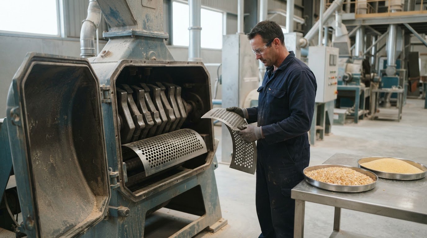
For hammer mill screen size selection, the opening sets the maximum particle size that can pass, but it doesn’t determine the average size or the full particle-size spread. For corn, a 3/32-inch (2.38 mm) screen is associated with an approximate particle size of 350-500 µm, while a 1/4-inch (6.35 mm) screen is associated with about 1,200-1,400 µm. Open area matters too: more open area can increase material flow and mill capacity, but may reduce screen strength and durability.

Choosing a screen means balancing target particle size, throughput and the material being milled. Smaller openings generally produce finer material, while larger openings can support coarser grinding and greater flow. Screen design, material friability and moisture also affect the result, so corn conversions are starting points, not universal settings.

This article explains how screen openings relate to particle size, how open area affects throughput, and how round-hole, slotted and other screen designs perform. It also outlines approximate corn-to-micron conversions and factors that can shift results in an operating mill.

Key Takeaways

  • Use target mean particle size and a material-specific reduction coefficient to estimate an initial screen opening, then refine the choice for the material’s behaviour.
  • Match the aperture to the material: grain, wood, fibrous feed and impact-heavy e-waste call for different screening considerations.
  • Balance open area against screen strength and durability; more open area can support flow, while a less open screen may favour screen life.
  • Compare round-hole, slotted and other screen designs by how they handle material flow, blinding and particle consistency.
  • Use corn-to-micron conversions as starting estimates, and account for operating conditions that can shift the resulting particle-size distribution.

What Does Hammer Mill Screen Size Mean?

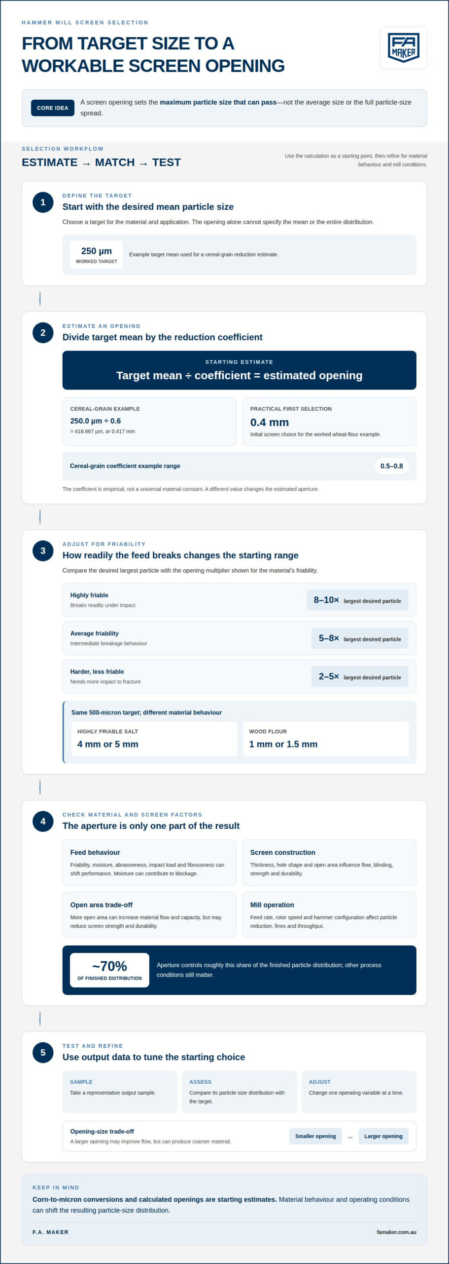
A screen opening sets the maximum particle size that can pass from the grinding chamber, but not the average size or the full particle-size spread. For a 250.0 µm target mean, a cereal-grain reduction coefficient of 0.6 gives a calculated opening of 416.667 µm, or 0.417 mm.

Estimating Screen Openings from Target Size

The reduction coefficient relates a target mean particle size to an estimated screen opening. Divide the target mean by the coefficient, then select a practical opening close to the result. For wheat flour, 250.0 µm divided by 0.6 gives 416.667 µm, or 0.417 mm; a 0.4 mm screen is the recommended initial selection for that worked example.

Matching Apertures to Material Friability

Friability describes how readily a material breaks under impact, and it helps determine the opening needed for a desired particle size. For highly friable material, openings can be 8 to 10 times the largest desired particle size; for average-friability material, use 5 to 8 times; for harder, less-friable material, use 2 to 5 times.

Material type narrows the starting range. Resins, minerals and chemicals use a 5x to 8x multiplier in the guide, while wood, fibre and grain hulls use 2x to 5x. A 500-micron target for highly friable salt is illustrated with 4 mm or 5 mm openings; the same target for wood flour is illustrated with 1 mm or 1.5 mm openings. Fibrous material may behave differently from brittle grain, even at the same aperture.

Using Screen Size to Shape Particle Distribution

Screen size influences particle distribution, but it cannot specify the average or spread on its own. The screen determines the maximum particle size able to pass, while hammer action and repeated contact reduce particles inside the chamber. Aperture controls roughly 70% of the finished distribution, so the remaining process conditions still matter.

Screen thickness, hole shape and open area affect flow and durability. Greater open area can increase material flow and capacity, but may reduce screen strength. Feed rate, rotor speed and hammer configuration also influence how particles encounter the hammers and screen, shifting fines and throughput without changing the aperture.

To reduce fines while improving capacity, take a representative output sample and assess its particle-size distribution. Then change one operating variable at a time. A larger opening may improve flow but produce coarser material; feed rate, rotor speed and hammer configuration can also affect particle reduction. Roller mills use a roll gap rather than a perforated screen. A tighter gap generally creates finer material, so adjust the gap against the target distribution.

How do I determine the optimal screen hole diameter for my specific material?

Begin with the material’s behaviour, target particle size and mill operating conditions. Grain, glass, wood and e-waste differ in friability, moisture, abrasiveness and impact load, so a single aperture or screen construction won’t suit every application.

Choosing Screens for Different Materials

Material-specific selection matches the opening and screen construction to how the feed breaks, flows and wears equipment. Grain is generally free-flowing, while wood and grain hulls can be fibrous; moisture can also contribute to blockage. Glass and e-waste require attention to impact and wear, particularly when the feed contains hard, non-friable pieces.

Typical openings range from 0.3 mm to 3 mm for sugar, salts and grains, and 3 mm to 12 mm for wood, fibre and grain hulls. Screens for e-waste recycling are often 1/4 inch or thicker to handle impact from non-friable material. Glass has no single opening specified here: the target distribution and the feed’s breakage behaviour guide the choice.

Selecting Screen Materials and Specifications

Screen material and thickness affect wear resistance, corrosion performance and the ability to withstand impact. Carbon steel screen holes typically range from 0.3 mm to 10 mm; stainless steel screen holes typically range from 0.6 mm to 5.0 mm. Choose material to suit the process environment, including abrasive particles or corrosive conditions.

For food-processing applications, specify the screen material and finish for the intended use; stainless steel alone doesn’t establish food-grade suitability. Screens are made in thicknesses from 24 gauge to 5/8 inch. Thicker material can better withstand impact, but a 1/2-inch-thick opening is more likely to catch slightly sticky or fibrous feed than a 1/8-inch-thick opening.

Matching Hole Size to Material Friability

Friability describes how readily a material fractures during milling and helps narrow the aperture for a target particle size. Highly friable feed breaks readily, while hard material may need repeated impact to reach the desired size. Compare the resulting particle-size distribution with the target instead of choosing an opening based on the material name alone.

For example, a 500-micron wood flour target is illustrated with a 1 mm or 1.5 mm screen. The opening is only a starting point: moisture, feed condition and mill settings affect how particles break and pass through. Fibrous material can bridge or catch in openings, so hole shape and screen thickness matter alongside diameter.

Preventing Screen Blockage and Damage

High moisture and agglomeration can blind screen openings. Drying or conditioning the feed can help reduce blockage. Abrasion and impact contribute to wear or damage, so regular inspection and timely replacement support milling efficiency and product quality.

Measure worn openings during inspection: replace a screen when holes have elongated by 5%. At a consistent feed rate, a 10% to 15% rise in motor amperage can signal a blinded or worn screen. Check for these changes alongside visible damage and altered output, then address the feed condition or screen wear causing the change.

For equipment context, review hammer mill screen applications alongside the material and target distribution.

Why is the open area percentage critical for throughput?

Open area is the proportion of a screen’s surface occupied by openings rather than solid material. It affects how readily particles pass through, making it central to balancing mill capacity and screen strength.

Open Area Effects on Mill Capacity

Open area describes the passage available for particles through a screen and influences how much material the mill can process. More open area can increase flow and capacity by giving particles more room to exit the grinding chamber. Less open area restricts passage and may reduce throughput even when hole size is unchanged.

Hole size and open area are related but distinct. A screen can retain a desired aperture while changing the spacing between holes. For example, a screen with 1/8-inch holes on 1/4-inch centres has 23% open area; with the same holes on 3/16-inch centres, it has 40%. The second pattern provides more open surface, but the choice still needs to suit the required capacity and screen strength.

For a given hole size, use the least open screen area that meets the capacity requirement. This avoids treating maximum openness as the only performance goal. A 20% open-area screen has 80% solid surface, illustrating how much of the screen remains material supporting the openings.

Balancing Screen Strength and Open Area

Increasing open area leaves less solid screen surface between openings, which can reduce strength and durability. This trade-off matters when impact or abrasive material puts greater demands on the screen. Lower open area may improve screen life but restrict throughput, requiring a balance between capacity and durability.

Square-hole screens offer the highest open area for a given hole size, making them suitable for maximising capacity with dry, non-abrasive material. They are not automatically the right choice for every application. Consider abrasiveness and impact, as well as the required particle-size distribution, before prioritising more openings.

Open Area and Airflow

Open area also provides routes for air to move through the screen alongside the material. A higher opening ratio can increase material flow and support pulveriser capacity, while a larger effective sieve area can improve screening efficiency. When openings become blocked, the available passage falls, disrupting particle movement and airflow.

Assess airflow alongside the material’s ability to pass through the screen, rather than relying on open-area percentage alone. A more open pattern, for example, may suit dry, free-flowing feed, while sticky or fibrous feed can obstruct openings. The aim is to pass the desired material at the required capacity while retaining enough solid area for the application.

Hammer Mill Screen Size: Choose Openings for Your Material

Round-hole, Conidur, slotted and herringbone screen types

Screen geometry affects how material moves through the grinding chamber, how openings resist blinding and the resulting particle-size distribution. Compare hole shape and layout as well as aperture size, particularly when milling fibrous or moisture-sensitive material.

Comparing Screen Hole Patterns

Screen patterns describe the shape and arrangement of openings, both of which influence passage and material flow. Round-hole screens are an industry standard for durability and consistent particle shape with free-flowing material. Slotted screens suit fibrous or high-moisture feeds because their openings can help prevent blinding and improve throughput.

Conidur and herringbone screens are other pattern options, but their names alone do not determine aperture or performance. Compare their opening geometry and layout with the feed and required particle-size distribution. Staggered hole patterns can promote a more uniform distribution and reduce blinding, so layout matters as much as hole shape.

Relating Screen Numbers to Hole Size

A screen number can describe the number of passages per inch rather than state an aperture directly. A screen-number designation may offer a rough guide to opening size, but it is not a direct measurement of the aperture. This gives a practical reference for interpreting the designation and relating it to the opening.

Use the stated hole dimension when matching a screen to a target, rather than relying only on its number. For example, a #6 designation describes the particular passage spacing and approximate hole size in that example. Checking both the number and the aperture helps avoid confusing screen labels with measured particle size.

Screen Hole Shapes and Size Ranges

Hole shape influences how material exits and how much open surface a screen provides. Round-hole screens typically have 30% to 60% open area. Square holes offer the highest open area for a given size and suit dry, non-abrasive material when capacity is the priority. A smaller opening generally retains particles longer during milling.

For fibrous or damp material, compare slotted geometry with round holes to manage blinding and throughput. For dry, free-flowing material, round or square openings may better support consistent passage or higher open area. Match the pattern to the application, then specify the hole shape, dimensions and arrangement.

Approximate corn screen-size-to-micron conversions

Corn screen openings offer a practical reference for estimating particle size during hammer milling. The conversions below show approximate associations for typical setups and feed applications. Use them to narrow a starting point, bearing in mind that the machine, material condition and operating settings also influence the finished size distribution.

  • 3/32 inch (2.38 mm): approximately 350-500 µm, associated with dairy use. This smaller opening is a reference for finer corn grinding.
  • 1/8 inch (3.18 mm): approximately 500-800 µm, associated with swine finisher feed. The range indicates that a single aperture can produce varied particle sizes.
  • 3/16 inch (4.76 mm): approximately 900-1,000 µm, associated with swine sow feed, poultry layers and broilers. It represents a coarser size than the 1/8-inch example.
  • 1/4 inch (6.35 mm): approximately 1,200-1,400 µm, associated with turkey feed. It gives a useful comparison point between finer and coarser corn products.
  • 3/8 inch (9.53 mm): approximately 1,600-1,800 µm, associated with ruminant feed. The wider opening supports a coarser target than the smaller listed screens.
  • 1/2 inch (12.7 mm): approximately 2,000 µm or larger, associated with coarse feeds and scratch grain. This is the largest opening in the conversion set.

To convert an opening from microns to millimetres, divide the micron value by 1,000. For example, 2,380 µm equals 2.38 mm. To compare the screen opening with the listed particle-size estimate, keep the units consistent: 350 µm is 0.35 mm, while 1,400 µm is 1.4 mm.

These figures describe approximate particle sizes, not a direct one-to-one conversion from aperture to finished particle. A screen opening determines which particles can pass through, while repeated impacts inside the grinding chamber affect the distribution below that maximum. That is why a 3.18 mm opening is associated with a 500-800 µm range, rather than one exact particle size.

When optimising a machine, treat the feed application as a starting reference and assess the product against its required size distribution. Moisture, feed rate, rotor speed, hammer configuration and screen condition can all influence output. If the product is too coarse, a smaller opening may reduce the passing size. If capacity is limited, assess throughput alongside the target rather than changing aperture alone.

Use the conversions to shortlist a corn screen, then match the opening to the required feed and operating conditions. Explore available hammer mills for equipment suited to corn processing.

F.A. Maker: Hammer Mills

F.A. Maker supplies hammer mills for processing applications where screen opening, target particle size and required throughput need to work together. Once you have established a suitable aperture and screen design, consider the mill as part of the wider production line, including the material being processed and the required product distribution.

Consider F.A. Maker when assessing a hammer mill for a new process or reviewing equipment needs around an existing line. Its processing equipment range also includes pin mills, ribbon blenders, pellet mills, pumps and valves, which may suit connected production requirements.

When discussing equipment options, share your material, target particle size and throughput requirements. Contact F.A. Maker to discuss hammer mills for your processing application.

Put the Screen Choice into Your Process Plan

Turn your screen decision into a clear equipment requirement by recording the material, desired output, current operating conditions and production objective. This gives hammer mill screen size selection a practical basis, connecting the opening choice to the process it needs to serve. As production needs change, focus the requirement on the product and operating conditions rather than treating a screen dimension as a standalone specification.

F.A. Maker supplies hammer mills and other processing equipment, including used stainless steel tanks, centrifuges and separators, and industrial mixers and blenders. If you’re assessing equipment for a process line, these offerings may be relevant alongside your milling requirements.

Contact F.A. Maker to discuss hammer mills for your process. A clearly defined requirement is a useful starting point for your next equipment decision.

Frequently Asked Questions

How does screen thickness affect milling efficiency?

Screen thickness affects how freely material exits and how well the screen withstands impact. A thick screen can obstruct sticky or fibrous feed more readily than a thinner one, while an overly thin screen may not withstand the application’s impact force. For example, a 1/2-inch-thick screen opening is more likely to catch slightly sticky or fibrous material than a 1/8-inch-thick opening. Balance passage with durability for the feed.

What is the difference between a screen and a bar grate?

A screen uses apertures to control which particles leave the grinding chamber, while a bar grate uses spaced bars to create discharge openings. The shape and spacing of either component affect passage and the resulting material. For a fine, controlled product, a perforated screen is commonly considered; a grate may suit a process focused on coarser discharge. Compare the required output and machine design before treating the two as interchangeable.

When should I choose a round hole screen versus a slotted or square hole screen?

Choose round holes for free-flowing material when durability and consistent particle shape matter. Slotted openings can help fibrous or higher-moisture feed pass without blinding. Square holes provide the highest open area for a given size and can suit dry, non-abrasive material when capacity is the priority. For example, consider slots for damp fibre, while dry grain may suit round or square apertures depending on the required throughput.

How does hammer mill screen hole size affect particle size and throughput?

A smaller opening generally holds material in the grinding chamber longer, which tends to produce finer output and can restrict throughput. A larger opening allows more rapid discharge and can support greater capacity, but the resulting product may be coarser. For example, a 3 mm screen produces finer particles than a 5 mm screen. The output distribution also depends on feed properties and operating conditions, not aperture alone.

What screen size should I use for hammer milling grain, feed, or biomass?

Choose an opening based on feed type, required product and animal stage or end use. For pig feed, the listed ranges are 1.2-1.5 mm for piglets, 1.8-2.0 mm for growers and 2.5-3.0 mm for finishers. Cattle feed uses 2.0-4.0 mm, while high-output coarse grinding of corn and biomass uses a 5 mm screen. Biomass fibre and moisture also affect passage.

How do hammer mill screen sizes compare for fine, medium, and coarse grinding?

Fine grinding uses smaller openings, while coarse grinding uses larger ones; medium settings sit between those requirements and depend on the target product. For ultra-fine grinding, openings of 1 mm or smaller are recommended, with 0.4-0.8 mm examples. A 5 mm screen is recommended for high-output coarse corn and biomass grinding. Match the aperture to the desired distribution rather than relying only on a fine, medium or coarse label.

How do I choose a hammer mill screen size for a target particle size or mesh specification?

A sound hammer mill screen size selection process starts with the target mean particle size and an appropriate reduction coefficient, then uses the calculation as an initial aperture estimate. For example, a cereal-grain target of 250.0 µm and a 0.6 coefficient calculate to a 0.417 mm opening, with a 0.4 mm screen as the initial selection. For mesh specifications, hammer mill screen size selection should focus on the required opening in microns or millimetres, since mesh number alone may describe passage count.

What are typical hammer mill screen sizes in millimetres and inches?

Screen openings vary by material and task. Common examples include 0.4 mm for an initial wheat flour selection, 1.2-3.0 mm for different pig-feed stages, and 5 mm for coarse corn or biomass grinding. Corn conversion examples include 3/32 inch (2.38 mm), 1/4 inch (6.35 mm) and 1/2 inch (12.7 mm). Check the actual aperture, since screen labels and hole dimensions aren’t always interchangeable.

How to Prepare a Site for Machinery Relocation and Reduce Damage Risk

Damage risk falls when site preparation for machinery relocation is treated as part of the move, not a last-minute clearance task. Assess both sites for floor capacity, ceiling height, doorway and corridor clearances, loading access, services and hazards. Before moving equipment, plan its shutdown, isolation, drainage, lifting and transport, assign responsibility for each stage, and record connections, condition and loose components.

Careful preparation helps prevent avoidable contact damage, spills and reassembly problems. It also gives everyone a clear sequence of work, from preparing the destination to confirming the machine is secured for transport.

This guide explains how to assess the route and destination, assign responsibilities and prepare machinery for removal. You’ll learn what to disconnect, drain, label and secure, and how to document the work so components can be identified during reassembly.

Each step focuses on practical decisions that reduce risk before, during and after the move, including site access, service isolation, lifting preparation and final inspection.

Key Takeaways

  • Survey the departure route and destination for access constraints, floor capacity, clearances, services and site hazards before the move.
  • Assign responsibility for each stage, from shutdown and disconnection through transport, reassembly and commissioning.
  • Assess equipment weight, dimensions and handling requirements to guide lifting and transport preparation.
  • Isolate utilities, drain relevant systems and secure loose or fragile components to reduce the risk of damage and spills.
  • Label and document connections and components so the equipment can be reassembled and checked methodically.

How do you minimise risk of equipment damage?

Minimise damage risk by assessing the equipment, both sites and every stage of the move before work begins. In Australia, involve competent machinery relocation specialists, electrical technicians, site engineers and lifting specialists, with each responsible for work within their expertise.

  1. Assess Machinery Before the Move

    Record each machine’s dimensions, weight, condition, connection points and handling requirements before planning its removal. Photograph the equipment, wiring and pipe connections, and label components that will be disconnected. Note fragile parts, exposed controls and existing damage so they can be protected and distinguished from damage during the move. Use these records to plan isolation, lifting and preparation.

  2. Review Destination Access and Infrastructure

    Survey the full route at both sites, including doorways, corridors, ceiling heights and loading docks. Compare clearances with the machine’s dimensions and planned handling position, not just its footprint. Assess floor load capacity, turning space, access constraints and the services required at the installation point. An obstruction or inadequate floor capacity can force changes to lifting or delivery arrangements and cause delays.

  3. Prepare Risk Assessments and Method Statements

    Write a task-specific risk assessment and method statement before physical work starts. Set out the sequence for isolation, disconnection, lifting and movement, then identify hazards such as electrical energy, restricted access and suspended loads. The NSW Work Health and Safety Act is the Work Health and Safety Act 2011 (NSW), according to NSW Government legislation register. Apply controls to the identified risks and allocate responsibility for each control.

    Have qualified personnel isolate energy sources before work on the equipment. After electrical isolation, test for a zero-energy state and label wiring for reconnection. Record who controls the isolation and how workers will confirm the equipment is safe to handle. These steps reduce the risk of unexpected operation during dismantling.

  4. Confirm Destination Readiness and Relocation Plans

    Inspect the destination before dispatch. Confirm the installation area is clear, the access route is usable, required services are available and the floor can support the equipment. Identify outstanding site work and assign an owner and completion point in the relocation schedule. Resolve these conditions before dispatch, as blocked access or incomplete infrastructure can interrupt installation and production.

    Coordinate site, equipment and transport responsibilities in one move plan. Include the work sequence, access arrangements, isolation status, lifting sequence and reinstallation needs. Share the current plan with everyone carrying out a task, and update it if site conditions change. A documented sequence helps teams work consistently and prevents conflicting activity around the equipment.

Why equipment must be properly disconnected before removal?

Disconnect machinery in a planned sequence before lifting or transport. Uncontrolled connections, retained fluids and poorly assessed loads can damage equipment or create handling hazards.

  1. Assess the machine’s weight, dimensions and handling requirements before selecting lifting equipment. Use equipment records and identification plates where available, and account for components that will remain attached during the lift. Industrial equipment can weigh several tonnes, so the load plan must reflect the actual machine configuration, not an estimate based on appearance.

    Record overall dimensions and identify protruding controls, pipework and fragile fittings. Consider how the machine will be turned, raised and moved along the available route. These details affect the lifting arrangement, transport position and tools needed to avoid impacts or uneven loading.

  2. Drain process materials and relevant fluids before removal. Hydraulic fluid, coolant and other contents can spill, add weight or shift inside the machine during transport. Place drained fluids in designated, labelled containers, then record quantities and disposal methods. Keep these records with the equipment documentation so the receiving team knows what was removed.

    Document every disconnection, including utility connections, removed fittings and component locations. Take clear photographs before dismantling, then label cables, hoses and loose parts for reassembly. Add a condition record noting visible damage before movement. These details provide a practical reference for handling and installation at the destination.

  3. Identify the centre of gravity and manufacturer-approved lifting points before rigging. Inspect lifting lugs and attachment points for damage, then confirm the machine remains stable and balanced as the load is taken. Do not attach slings or chains to frames, guards or pipework simply because they look convenient. Incorrect attachment can distort components or cause the load to shift.

    Select cranes, forklifts or hoists to suit the load and movement. Hydraulic jacks, rollers and dollies can assist with manoeuvring where suitable. Inspect lifting equipment and rigging gear before use, and select rated securing equipment appropriate to the planned lift. Qualified handlers should coordinate the lift and keep personnel clear of the suspended load.

  4. Inspect the machine and work area before handling begins. Secure loose parts, remove fittings that could catch, and protect fragile components from contact. Personnel involved in the move need appropriate protective equipment, including safety helmets, gloves and safety boots. They should understand the agreed lifting sequence and communication signals.

    Finish with a pre-transport inspection: account for components, confirm disconnections, and check that the machine is ready to move. A documented handling plan supports industrial machinery relocation planning and gives the receiving team a clear record of preparation.

Move planning, timelines and team responsibilities

Plan the move as one sequence, from dismantling and transport through installation and commissioning. In Australia, permit and road-access requirements depend on the load and route. Coordinate them with the safety plan before scheduling machinery movement.

Oversized or overweight loads may require approvals. The plan should also address heavy-vehicle mass limits, fatigue management, hazardous-goods rules and state-specific road restrictions.

  1. Assign Move Planning Responsibilities

    Appoint a coordinator to maintain the schedule and share changes with site and transport teams. Assign separate owners for equipment preparation, rigging, vehicle access, destination readiness and installation. Record who can stop work if conditions change, such as an obstructed route or unstable load.

    Include relevant specialists in the planning process. A qualified rigger can plan the lift, while site personnel coordinate access and production requirements. Identify who controls hydraulic equipment, manages isolation and receives the machinery. Clear responsibilities prevent missed handovers between dismantling, transport and reassembly.

  2. Plan the Route and Review Load Regulations

    Map the complete journey from the loading area to the destination, including site exits, public roads and final access. Compare the transport configuration with route constraints such as bridges, turning areas, overhead clearances and road restrictions. For an oversized load, identify required approvals, approved routes, travel times and escort arrangements before confirming dispatch.

    Check whether the journey crosses state borders, as permitted routes and operating conditions can differ between jurisdictions. Consider the freight’s weight, dimensions and sensitivity when selecting the vehicle and rigging arrangement. Record route decisions in the move plan, and assess the actual load rather than assuming a familiar road is suitable.

  3. Schedule Relocation and Downtime

    Build the schedule around linked tasks: shutdown, disconnection, lifting, transport, installation and commissioning. Record which production activities depend on the machine, then plan its removal for a period that limits disruption. Allow time for destination access, delivery coordination and reassembly instead of scheduling transport as an isolated event.

    Mark dependencies that could delay the move. For example, do not dispatch transport before the destination installation area is ready. Set update points for the coordinator, production team and transport contact, and communicate changes promptly. A visible schedule helps affected teams plan around the equipment’s absence.

  4. Confirm Scheduling and Relocation Plans

    Review the final schedule with site personnel, transport partners and those responsible for installation. Confirm the sequence, access arrangements, contact roles and handover points. Include contingencies for route changes, delayed access or weather affecting lifting work, and specify how updates will reach each team.

    Keep one current move plan, with task owners and completion status. Before dispatch, confirm that transport, rigging and destination preparations align. At delivery, record receipt and pass the equipment documentation to the installation team. This organised handover supports commissioning and helps production staff plan the return to operation.

How to Prepare a Site for Machinery Relocation and Reduce Damage Risk

Disconnecting, draining and securing machinery components

Shut down machinery in a controlled sequence, then isolate and disconnect its services before removal. In Australia, follow applicable WHS requirements and Australian Standards for the specific machinery, guarding and electrical work. Qualified personnel should identify the requirements relevant to the task.

  1. Shut Down and Disconnect Machinery

    Follow the machine’s shutdown procedure and remove process materials before dismantling connections. Isolate energy sources, then verify the equipment cannot operate before anyone handles cables, hoses or fittings. Label each connection at both ends and photograph its position so the receiving team can identify where it belongs during installation.

    Record the disconnection sequence and note any component removed for transport. For a bottle filler, for example, identify connected services and protect exposed connection points after removal. Keep the record with the equipment so installation personnel can match connections to the correct machine.

  2. Disconnect Electrical and Utility Services

    Arrange electrical isolation through qualified personnel, then test for a zero-energy state before work proceeds. Label wiring clearly for reconnection, and protect cable ends from impact and contamination. Shut off compressed air at its supply and depressurise the system before disconnecting hoses or fittings.

    For water and cooling systems, shut off the supply, drain the piping and contain residual water. For gas lines, close the source, cap connections and purge lines if needed. These service-specific steps help limit leaks and spills during handling and transport.

  3. Drain hydraulic fluid, coolant and other relevant process fluids before moving the machine. Collect each fluid in a designated container, label it and store it safely. Document fluid quantities and disposal methods, and keep the records with the move documents. Removing residual contents helps prevent leaks, reduce transport weight and limit internal movement that could damage equipment.

    Secure loose parts and remove fittings that could catch on rigging or transport restraints. Protect fragile components, including guards, sensors and exposed control panels, with suitable padding—specialists such as Foam Packaging Direct supply custom protective foam packaging to cushion delicate parts during transport. Keep small parts together in labelled packages, and record their connection or mounting locations for accurate reassembly.

  4. Complete a final disconnection inspection before the equipment leaves the site. Confirm utilities are disconnected, fluid containers are accounted for, open connections are protected and all components are present. Check the machine’s condition against pre-move photographs. This record helps distinguish existing marks from damage during logistics and supports a controlled handover.

    Keep isolation, fluid and condition records together. Clear labels and photographs give installation personnel useful references when reconnecting electrical services, air lines, water piping and gas connections. Reconnection should follow the equipment’s installation instructions and applicable requirements identified for the work.

Decommissioning and machinery preparation

Decommissioning involves more than disconnecting services. Careful planning protects components during dismantling, prepares the machine for transport and leaves both sites ready for the next stage.

  1. Break down the machine only as much as needed for safe transport and installation. Follow its configuration records, identify each assembly and label parts before separating them. Package dismantled components so they cannot shift, rub together or get mixed with parts from another machine. Keep fasteners and small fittings with their labelled assemblies.

    Protect exposed surfaces and delicate components from impact, dust and moisture during handling. Secure doors, guards and movable sections in their transport positions. Keep a component register recording what was removed, how it was packed and where it belongs. This gives the installation team a clear sequence to follow at the destination.

  2. Prepare the machine for transport with restraints suited to its shape and configuration. Use engineered strapping, padding and load-rated anchors at appropriate points, with vibration-control measures where needed. Do not place restraints across vulnerable controls, pipework or unsupported panels. Check that packaged parts and attachments cannot move against the main frame during loading or travel.

    For machinery shipped internationally, corrosion protection matters because cargo may spend weeks in humid maritime environments. Protect suitable surfaces and openings before packing, while keeping identification marks and inspection points accessible. Match the protective approach to the machine’s materials and expected transit conditions.

  3. Prepare the former installation area after machinery removal. Clear debris and leftover materials, then arrange disposal according to applicable requirements. Fill holes and address uneven surfaces through suitable grinding or levelling. Assess the floor’s load-bearing integrity before placing other equipment or returning production to the area.

    At the destination, compare the installation area with the machine’s layout and connection requirements. Reassembly should follow the manufacturer’s instructions, with the equipment correctly aligned and levelled. Keep assembly records available as components are fitted, and resolve mismatches before reconnecting services or beginning operation.

  4. Plan a documented handover after installation. Record the final configuration, relevant compliance records and any changes made during reassembly. Commissioning should include functional testing, calibration and performance checks before production resumes. Familiarise operators with the relocated equipment, including its controls and any changed operating arrangements.

    Careful records connect dismantling decisions with installation checks, reducing uncertainty when the machine returns to service. For help coordinating machinery preparation and relocation, discuss machinery relocation services.

F.A. Maker: Used Stainless Steel Tanks

F.A. Maker can help when machinery relocation leads you to review processing equipment needs at the destination. Its range includes Used Stainless Steel Tanks, Centrifuges and Separators, Industrial Mixers and Blenders, and Pumps and Valves.

Consider these categories when replacing equipment, planning a production-line change or deciding which machinery to install alongside relocated assets. Match the equipment type to the process and available site infrastructure, then plan access, installation space and service connections before delivery. This connects equipment selection with the preparation work covered in this guide.

For information about equipment options for your operation, contact F.A. Maker or visit famaker.com.au.

Set the move up for the next stage

Use the relocation plan to make the next decision: will the existing production line be reinstalled as it stands or adjusted for the destination? That choice affects equipment selection, layout and the work needed before production resumes. Keep operational requirements in the move plan rather than treating equipment replacement as a separate decision.

F.A. Maker offers Used Stainless Steel Tanks, Centrifuges and Separators, and Industrial Mixers and Blenders. These categories may be relevant when reviewing processing equipment alongside site preparation for machinery relocation. Consider how each option fits the process and available installation space before moving the project forward.

When you’re ready to discuss equipment for the move, contact F.A. Maker about your move. A clear next step helps turn careful preparation into a workable plan for the site and its production needs.

Frequently Asked Questions

How long does industrial relocation take?

Industrial relocation time depends on the machine, dismantling scope, transport route and destination readiness. A single machine with clear access requires a different schedule from a production line needing staged removal and reassembly. Include time for route approvals where needed, installation and commissioning, not just vehicle travel. Map dependencies such as site works and production shutdowns before setting the move window.

What Does Site Preparation Involve?

Site preparation means making the work area accessible, stable and ready for its intended use. At an industrial site, this can include clearing obstructions, establishing access routes, checking drainage and assessing ground or floor condition. Plan where materials and equipment will be staged so they do not block vehicle movement or work areas. The work required depends on the site’s existing condition and planned activity.

What does site preparation for machinery relocation involve?

Preparation covers both the removal area and the destination, making each ready for the machine’s movement and installation. Define the equipment footprint, installation orientation and space operators need to access the machine after placement. Identify any base or anchoring work, along with the services required at the final position. A layout drawing can help coordinate site work, transport access and the production-line arrangement.

What site survey and access checks are needed before relocating machinery?

Survey the route from the machine’s current position to the loading point, then inspect access at the destination. Measure doorways, corridors, ceiling clearances and loading areas against the machine’s transport dimensions. Note turns, obstructions, uneven surfaces and shared access that could affect movement. Record where the vehicle can load and unload, and whether the destination can receive the machine in its planned orientation.

What floor loading capacity and foundations are required for relocated machinery?

The required capacity depends on the machine’s operating weight, support points and foundation design. A machine on concentrated feet can load a floor differently from one supported across a broad base. Account for the equipment configuration during operation, not just its unloaded transport condition. Assess the floor or foundation against the machine’s installation information, then complete any reinforcement or levelling work before positioning it.

What electrical, compressed air, hydraulic and utility connections must be prepared?

Prepare the connection points and routes specified for the machine, including electrical supply, compressed air, hydraulic services, water, cooling and gas where applicable. Align connection locations with the final layout so lines do not obstruct access or maintenance areas. Use the machine’s installation documentation to identify connection requirements and interfaces. Leave enough working space around service points for safe installation, isolation and later inspection. For property and business owners also evaluating power infrastructure for residential sites, Makn Energy provides solar panel and battery storage solutions across Adelaide.

What lifting equipment, transport access and clearances are needed for machinery relocation?

The lifting arrangement depends on the load’s weight, dimensions, centre of gravity and approved lifting points. Cranes, forklifts or hoists may suit different moves; jacks, rollers or dollies can help with positioning. Assess route clearances for the machine in its actual lifting or transport configuration. Confirm vehicle access, loading space and unloading position, then coordinate rigging with site constraints and the planned movement sequence.

What are the steps and timeline for preparing a site for machinery installation?

Start with a site survey and machine layout, then identify access, floor and service work. Schedule clearing, foundation preparation or utility changes before delivery. Next, confirm the installation area is ready and coordinate unloading and positioning through the move plan. Include assembly, alignment, service connections and commissioning in the sequence. The overall timeline depends chiefly on site work, equipment configuration and access readiness.

Used Disc Stack Centrifuge for Sale: Separation and Sourcing

The key difference is the material being separated: liquid-liquid separation divides liquids of different densities, while liquid-solid separation removes suspended particles from a liquid. A used disc stack centrifuge for sale can perform either task by spinning the feed through stacked conical discs, generating centrifugal forces of around 5,000 to 15,000 × g. Denser material moves outward in the bowl, while the lighter liquid moves towards the centre.

That principle is straightforward, but the right machine depends on the feed and the separation required. A unit designed to clarify liquid may not suit separating two liquid phases. Bowl design, discharge arrangement and construction materials all affect whether it fits your process.

This article explains how disc stack separation works, which components and materials to assess, and how to source a used disc stack centrifuge for sale in Australia. It also compares liquid-liquid and liquid-solid duties, helping you judge a centrifuge by its configuration and process fit, not its name alone.

Key Takeaways

  • Match the centrifuge’s separation duty to the feed: liquid-liquid and liquid-solid processes rely on different configurations.
  • Understand how bowl design, discharge arrangement and operating conditions influence separation performance.
  • Compare capacity and operating specifications with your process requirements rather than relying on machine type alone.
  • Assess used and new-surplus equipment by its condition, configuration and suitability for the intended duty.
  • F.A. Maker offers centrifuges and separators, along with used stainless steel tanks and other process equipment.

How does the separation process occur inside the disc stack bowl?

Inside the bowl, rapid rotation creates centrifugal force that separates materials according to density. Disc stack centrifuges can generate around 5,000 to 15,000 × g, moving denser material outward while lighter liquid travels inward. The feed enters through a central inlet and spreads between closely spaced conical discs. These discs shorten the distance particles must travel before separating from the surrounding liquid.

As feed moves through the disc stack, heavier suspended solids migrate towards the bowl wall. In liquid-liquid separation, the denser phase moves outward and the lighter phase towards the centre. Separate outlets collect the clarified liquid or separated liquid phases. The bowl and discharge design determine whether solids leave intermittently or through a continuous discharge.

Feed preparation affects separation. Pre-straining removes coarse particles that could obstruct the inlet, disrupt flow or add unnecessary solids to the bowl. Choose a strainer to suit the feed’s particle size and composition. For example, a food-processing stream with visible plant fragments needs different preparation from a fermentation broth containing fine suspended material.

Food and beverage applications include milk and cream separation, wine processing, oil purification and fermentation broth clarification. In dairy processing, a separator divides milk into cream and skim milk. In wine processing, clarification removes suspended material. In each case, the feed’s properties and required output matter more than the centrifuge’s nominal capacity alone.

Pharmaceutical and biotechnology processes may use disc stack centrifuges to clarify fermentation broth or harvest mammalian cells from culture. Chemical processing may use them to separate liquid phases or remove fine solids. The same bowl principle serves these duties, but product sensitivity, solids loading and required clarity affect the operating configuration.

Solids loading matters because a disc stack centrifuge is limited to about 8% solids. A stream above that level may require another separation approach, such as a decanter centrifuge, which is designed for higher solids content. The appropriate choice follows from the feed and separation objective. A machine selected for fine clarification may not suit a thick slurry or a process requiring substantial solids removal.

Discharge design affects whether a process can run continuously. Self-cleaning bowls release accumulated solids at intervals, while nozzle designs can eject concentrated solids continuously. The right arrangement depends on whether solids settle and how the process handles discharged material. In brewing, for example, a disc stack centrifuge can separate yeast from beer for reuse or removal.

How does the centrifuge handle liquid-liquid versus liquid-solid separations?

The bowl separates material by density, while the outlet and solids-discharge design must suit the feed. A two-phase duty separates two liquids or a liquid from solids. A three-phase duty separates two liquids and solids.

Two-Phase and Three-Phase Separation

Two-phase separation produces either two liquid streams, such as oil and water, or clarified liquid and concentrated solids. Three-phase separation divides the feed into a lighter liquid, a heavier liquid and solids. Each phase needs an appropriate outlet and discharge path. An oil-water-solids feed, for example, requires all three fractions to leave the bowl separately.

Clarifiers, Separators and Bowl Designs

A clarifier removes suspended solids from liquid; a liquid-liquid separator divides phases of different densities. A desludger handles feeds that accumulate solids and need periodic removal. These names describe different duties and discharge arrangements, not guaranteed performance. Match the configuration to the feed: wine clarification prioritises liquid clarity, while oil purification separates liquid phases.

Nozzle bowls discharge solids continuously through outlets in the bowl. They suit processes where concentrated solids can flow out continuously. Other designs retain solids until they are discharged intermittently. This choice affects process continuity and solids collection. A steady solids load creates a different duty from a mostly liquid stream with occasional particles.

Fine-Particle Separation

Stacked conical discs create thin flow passages, helping particles travel towards the bowl wall over a shorter distance. A disc stack centrifuge can capture particles as fine as 0.6 µm. This capability is relevant to fine suspensions, including microalgae cells separated from culture medium. The result depends on particle size, density difference, feed flow and the bowl’s operating configuration.

Centrifugal force moves denser material outward and lighter liquid inward. In liquid-liquid service, the interface between phases must stay positioned so separate outlets collect each stream. In liquid-solid service, particles move outward and clarified liquid exits separately. Feed volume and solids concentration affect the load on the bowl and how discharge must be managed.

Efficiency, Product Quality, and Requirements

Separation efficiency describes how effectively the machine divides the target phases; product quality depends on the purity or clarity required downstream. At the calculated minimum particle size, sigma theory indicates approximately 50% separation efficiency. That figure highlights why the target particle size matters when assessing a duty, rather than treating clarity as a simple yes-or-no result.

For an Australian installation, assess applicable electrical and workplace safety requirements, including guarding, isolation, commissioning and operating procedures. Bowl rotation, electrical supply and solids discharge all need to fit safely within the plant process. For example, the layout should provide access to the bowl and a suitable route for collecting discharged solids.

What is a disc stack centrifuge and what are its core components?

A disc stack centrifuge separates process streams inside a rotating bowl. Its main components include a feed inlet, spindle, drive, bowl, disc stack, liquid outlets and solids-discharge arrangement. The drive turns the spindle and bowl, while the inlet directs feed into the separation zone. Conical discs create narrow passages through which the flow separates. Bowl design and operating speed must suit the process.

The discs are stacked with spacing that can range from 0.4 to 2 mm. Their conical shape creates a large effective separation area within a compact bowl. Disc angles commonly sit around 40 to 50 degrees. Bowl diameters can range from around 7 to 24 inches or more, depending on equipment design. These dimensions affect the available separation area and the machine’s process capacity.

Capacity is duty-specific. Dairy cream separation applications can run around 5,000 to 10,000 L/hr, while a listed Alfa-Laval PX 55 separator operates at 6250 RPM. Another example, the GEA Westfalia GSE 125-06-777, has a bowl speed of 5900 rpm. These figures describe different machines and applications, not a single standard operating point. Feed properties and process requirements determine the relevant combination of speed and throughput.

The bowl also determines how solids are retained or removed. A solid-wall design holds solids within the bowl until discharge, while a nozzle arrangement can eject concentrated solids continuously. Liquid outlets collect separated product streams. For example, the Westfalia BKA-35-86-076 solid-bowl disc centrifuge has a maximum bowl speed of 5000 rpm. Bowl design therefore influences both discharge handling and the process’s operating pattern.

Cleaning is part of process configuration, especially where product changeovers matter. A bowl-rinsing cycle uses a process-compatible liquid to flush residues from internal surfaces and disc passages. The cleaning sequence needs to cover the bowl, disc stack and product-contact pathways. In pharmaceutical processing, removing residues between batches supports controlled product transitions. Cleaning access and discharge design also affect how the machine fits the plant’s routine.

Compare bowl speed, disc arrangement, throughput and discharge type with the actual feed. High RPM alone does not establish suitability: the bowl must also handle the required volume and solids behaviour. A dairy separator set up for cream separation, for example, has a different duty from a pharmaceutical clarifier. The benefits of a disc stack design depend on matching its core specifications to the process.

Used Disc Stack Centrifuge for Sale: Separation and Sourcing

Used and new-surplus equipment sourcing

Used and new-surplus centrifuges differ in history, condition and configuration. Assess each machine against the process duty and the work needed before installation.

Condition and Refurbishment

Condition describes the machine’s present state, while refurbishment covers work to restore or adapt it. This distinction matters because a complete-looking centrifuge may still lack process-critical parts. For example, a listed Westfalia SA14-06-076 clarifier is missing its bowl, a major component that affects whether the equipment can perform its intended duty.

Assess the bowl, disc stack, drive, controls, outlets and discharge arrangement individually. Wear, corrosion or damage to product-contact surfaces can change the refurbishment scope. A used Alfa Laval unit may have a different configuration from the same model set up for another process. Record the required clarification duty and compare it with the equipment’s actual configuration.

Costs and Lead Times

Refurbishment and maintenance costs depend on the machine’s condition, required parts and work scope. Request a quote: bowl damage, bearings, seals, controls and labour can all affect the estimate.

Used equipment lead times are measured in days or weeks, rather than the months often required for new disc centrifuge orders. New-surplus equipment offers another sourcing route: it is unused stock, but storage history and supplied configuration still matter. Compare delivery timing with the work needed to prepare the machine for its intended process.

For example, an Alfa Laval MAB-104B-24 lube oil centrifuge purifier is listed with a 1.5 kW motor. The motor specification alone doesn’t establish suitability. Bowl condition, outlet arrangement and compatibility with the feed also shape the practical refurbishment and installation scope.

Purchase Risks and Warranty Terms

Purchase risk is the possibility that condition, configuration or missing components differ from the needs of the process. This matters because repair work or a required replacement can affect the machine’s overall suitability. The Westfalia SA14-06-076 example shows why a missing bowl is more than a cosmetic issue.

Purchase documents should identify the equipment supplied, its condition and any completed refurbishment. They should also specify whether a warranty applies and, if so, its duration, coverage and exclusions. A warranty’s value depends on those written terms, not the model name alone. Make the scope clear for components such as the bowl, drive and controls.

New-surplus machines still need a configuration review. Check that the supplied bowl and discharge arrangement match the separation duty, then account for required process connections and commissioning. For used equipment, maintenance records and test results help establish operating history. They provide useful context but do not replace an assessment of the machine’s current condition.

Compare options by how ready they are for the job, not just by acquisition timing. A unit requiring a bowl replacement presents a different project from a complete centrifuge with a suitable configuration. For Australian plants, include transport, installation and integration with the existing process line in your sourcing plan.

Materials of construction and sanitary designs

Material selection affects product contact, cleaning and service life. In food, beverage and pharmaceutical applications, the bowl, discs and wetted outlets need materials suited to the feed and cleaning process. Stainless steel is common in process equipment because it resists corrosion in many operating environments. However, the grade alone cannot establish whether a machine suits a particular product or cleaning routine.

Two listed centrifuges provide specific material examples: the Westfalia SIG 15007 nozzle-type disc centrifuge and the Delaval BRPX-207-39S automatic disc centrifuge are made of 316 stainless steel. Those model details can help frame an equipment assessment, but they don’t describe every component or establish the condition of a used machine. Inspect product-contact parts and compare their material with the process fluid, cleaning agents and operating conditions.

Surface condition matters as much as alloy selection. Scratches, pitting, deposits or damaged welds can complicate cleaning and leave places for product residues to collect. Inspect the bowl, individual discs, feed zone and liquid outlets. For example, residue between discs can be difficult to remove if the stack is damaged or assembled incorrectly.

Sanitary design combines material, geometry and access for cleaning. Smooth product-contact surfaces and drainable passages support effective cleaning, while crevices and retained liquid can make it harder. Review how the machine opens, how the bowl and disc stack are accessed, and how cleaning liquid moves through the process path. These details are particularly important when product changeovers require a defined cleaning routine.

Construction must also suit the solids stream. Abrasive particles or concentrated sludge create different wear conditions from a low-solids liquid. A decanter centrifuge may suit heavier solids loading, while a disc stack design may fit fine clarification. The right choice depends on the feed, required separation and equipment configuration.

Manufacturers specify materials and surface finishes for particular designs, so assess the actual machine rather than relying on its brand or model family. Check that the bowl, discs, gaskets and outlet components suit the intended process. Confirm that the surfaces can be cleaned using the plant’s established method, and consider how continuously the machine will operate. These checks help identify whether refurbishment or component replacement is needed.

For an equipment assessment, record the material grade, condition of product-contact surfaces, cleaning access and signs of corrosion. A written inspection can distinguish cosmetic wear from defects affecting process suitability. To discuss related process equipment, explore available decanters for duties involving concentrated solids.

F.A. Maker: Used Stainless Steel Tanks

F.A. Maker supplies centrifuges and separators for industrial separation duties, as well as used stainless steel tanks. Turn to F.A. Maker when assessing equipment for a process line and considering how a centrifuge fits with storage, mixing or fluid transfer requirements.

Matching the centrifuge with related equipment helps clarify what the full line needs. Industrial mixers and blenders support process preparation, while pumps and valves handle fluid movement and control. The right combination depends on the feed, process sequence and required output.

Contact F.A. Maker to discuss your equipment requirements and how a centrifuge or separator could fit into your process.

Set your next process decision in motion

Before shortlisting a used disc stack centrifuge for sale, define its process duty and the outcome your line requires. Then compare that with the equipment’s configuration, condition and fit with surrounding plant systems. This gives your team a practical basis for weighing options and identifying the information needed to make a purchase decision.

Consider the centrifuge as one part of the production line. Feed preparation, storage, transfer and downstream handling all affect how equipment works together. Mapping these connections can show whether your priority is separation alone or a broader process-equipment requirement.

F.A. Maker can help you explore centrifuges and separators alongside other process equipment relevant to your plant. If you’re ready to discuss the application and equipment requirements, contact F.A. Maker about centrifuges. A clear description of your process and intended duty is a useful place to start.

Frequently Asked Questions

What are common operational challenges or maintenance factors?

Vibration, uneven solids discharge and deposits on product-contact surfaces are common factors to monitor. Vibration readings around 2 mm/s to 4 mm/s can signal that maintenance is needed; levels exceeding 7 mm/s may warrant immediate shutdown. Changes in feed composition can also affect operating stability. Keep a record of vibration trends, cleaning observations and discharge behaviour to help distinguish gradual wear from a developing fault.

What role do the stacked discs play in particle separation?

The stacked discs create thin channels, increasing the area available for particles to separate from liquid. Disc spacing and surface condition influence flow through the bowl. Deposits or damaged disc edges, for example, can disrupt flow through the stack. During inspection, look for even spacing, clear passages and wear that could affect separation consistency.

Where can I find a used disc stack centrifuge for sale in Australia?

F.A. Maker supplies centrifuges and separators for Australian process operations. To narrow your search, define the feed, separation duty, plant connections and preferred discharge arrangement. This gives you a practical basis for comparing equipment with your process instead of relying on a model name alone. Plan transport and installation around the destination site and its existing production line.

What is the price of a used disc stack centrifuge in Australia?

The price is provided after a quote request and depends on the machine, its condition and the work required for the intended duty. Bowl completeness, drive configuration, controls, refurbishment and transport can all affect the overall project cost. Request pricing in Australian dollars and compare equipment on its required preparation as well as its purchase price. A machine needing major component work has a different cost profile.

Which used disc stack centrifuge brands and models are available in Australia?

Used equipment examples in the market include Alfa Laval, GEA Westfalia and Delaval models. Models and configurations vary, so treat a model name as a starting point, not proof of suitability. Clarifiers, separators and nozzle-type bowls, for example, perform different duties. F.A. Maker supplies centrifuges and separators; compare a machine’s configuration with your feed and process requirements.

How should I compare capacity, bowl speed and throughput?

Compare capacity and bowl speed under the same process duty and feed conditions. Rated throughput alone does not establish how a machine will perform with your product. Review required flow, solids load, separation target and operating configuration together. A stated capacity for dairy cream separation, for example, is not a direct rating for a different liquid or solids mixture.

What inspections and service records should buyers request for a used centrifuge?

Request records identifying the machine and documenting maintenance, repairs, operating history and refurbishment. Inspect the bowl, disc stack, drive, controls, outlets and discharge components for wear, damage or missing parts. Compare the configuration with the intended duty, then record any work needed before installation. Clear documentation helps distinguish observed condition from assumptions based on age or brand.

Typical refurbishment and maintenance costs for used disc stack centrifuges

Vibration readings around 2-4 mm/s can signal that maintenance is needed.

Finding Reliable Used Machinery Dealers for a Sound Purchase

Finding reliable used machinery dealers means looking beyond the listing to the machine’s service and repair history, the seller’s track record, and the support available after purchase. Used equipment can pass through previous owners, dealers or online platforms before inspection, sale and transport to your site. A sound purchase depends on understanding each handover and confirming the machine’s condition and sale terms in writing.

A low asking price or polished listing can’t show how consistently a machine was maintained, whether its parts are practical to source, or what happens if delivery is delayed. Assess the equipment and the seller together, then compare the full purchase terms rather than relying on a single claim.

This guide explains how to review service records, assess sellers and online platforms, and compare parts availability and ongoing support. It also covers inspections, delivery arrangements and the details to document before you commit, helping you judge whether a used machine fits your operation.

Key Takeaways

  • Compare service records with the machine’s serial number, operating hours and reported condition to identify gaps in its history.
  • Assess sellers through references and feedback, then compare what each platform actually documents about the equipment and sale terms.
  • Check parts access and support needs against your operating schedule before choosing a machine.
  • Put the agreed condition, liabilities, payment and delivery arrangements in writing before committing.
  • Use a structured inspection to assess wear, leaks, damage and operating performance, including after the machine arrives.

1. Service and repair history?

Start with the machine’s service and repair history, then test whether the seller’s claims match its records. Ask for dated maintenance entries, repair invoices, operating hours and details of replaced components. Compare the serial number on the machine with the number on its records. For construction equipment, a history of hydraulic repairs or repeated electrical faults can signal further inspection is needed. Missing records don’t prove poor maintenance, but they leave more of the machine’s past unverified.

Assess the dealer as carefully as the equipment. Look for a consistent business name, physical address, working telephone number and clear arrangements for viewing machinery. Check the dealer’s reputation across multiple sources, including both positive and negative feedback. Ask for references from previous buyers of comparable equipment, then ask about the accuracy of the description, paperwork and delivery. Specific examples are more useful than general praise.

Confirm that the seller’s business details and location make sense for the sale. A seller offering a machine for inspection should be able to explain where it is held and how access is arranged. Compare the business details on the listing, invoice and contract. If the named seller changes between documents, pause and establish which entity is responsible for the sale before paying.

For used machinery bought from a dealer in Australia, the Australian Consumer Law may apply. Consumer guarantees depend on whether the buyer and purchase meet the law’s definition of a consumer, so business machinery purchases aren’t automatically covered in the same way as household purchases.

Check replacement-parts availability by identifying the machine’s make, model and serial number, then locating the parts needed for planned maintenance. Ask which components have already been replaced and whether the seller can identify compatible parts. A machine with a sound repair record may still cause operational problems if a critical seal, control component or motor is difficult to source. Include likely supply delays in your assessment of downtime risk.

Before signing, read the contract for the stated condition, known faults, included accessories, payment milestones, liability and delivery responsibilities. Make sure any verbal promise, such as a listed repair or included component, appears in writing. Confirm who arranges transport, who is responsible for unloading and how transit damage will be recorded. Compare the agreed delivery location and timing with your site’s access and handling requirements. Keep the signed contract, inspection notes and relevant service records together as the purchase file.

2. How to find trustworthy used machinery suppliers online?

Online listings are a starting point, not an inspection. Ask the supplier for records that connect the machine’s identity, condition and maintenance history. Useful documents include the make, model, year, serial number, operating hours, service entries, repair invoices, known faults, included accessories and any inspection report. Check that the serial number on the machine matches the paperwork and listing.

For machines with telematics, ask for a report showing logged hours, fault codes and maintenance events. Many Cat, Komatsu and Volvo machines manufactured after 2018 have onboard telematics that record this information. Compare the report with service records and the hour meter. A mismatch needs an explanation before you assess condition or value.

Ask whether a warranty applies, what components it covers and how claims are handled. For used construction equipment, one recommendation is to request a written mechanical warranty covering the engine, transmission and hydraulics for 30–90 days. Put the duration, exclusions and claim process in the contract. A verbal assurance doesn’t define what the seller must address.

Documents alone can’t show how machinery performs. Arrange an on-site inspection, or use an independent specialist familiar with the machine type. If distance prevents a visit, request a live video tour showing startup, operation and close views of key functions. Ask the operator to show the controls, guards, connections and areas identified in the inspection records.

Tailor the inspection to the equipment. For construction equipment, observe movement under load and listen for unusual engine, transmission or hydraulic noises. For electrically driven machinery, test the controls and operating functions, and look for damaged wiring, loose connections or fault indicators. Check structural areas for cracks, corrosion, leaks and signs of repair. Match observed wear with reported hours and maintenance entries.

For Australian safety checks, the AS/NZS 4024 series is a reference for reviewing machinery guarding. Australian work health and safety laws require risks from plant to be identified and managed regardless of the plant’s age. Check guarding and operating controls against the machine’s intended use, then document any corrective work needed before installation or operation.

To check ownership and possible liens, match the seller’s legal name and machine identifier across the listing, invoice and ownership documents. Request written confirmation of authority to sell and disclosure of any security interests, then use the serial number or vehicle identifier to search the relevant Australian register before payment. For recalls, ask the manufacturer to check the serial number against its recall records.

Red flags include refused inspections, missing serial numbers, inconsistent records or pressure to pay before documentation is complete. An online listing priced more than 20–25% below comparable market listings is a major fraud warning sign. Pause the transaction and resolve discrepancies before proceeding.

3. Choosing reputable B2B and used-machinery platforms

A B2B platform is a discovery channel, not necessarily the machinery seller. Before relying on a listing, identify the legal business offering the equipment and the platform’s role in the transaction. For example, a marketplace may host an advertisement while the seller controls the inspection, contract, payment and transport. Confirm which party receives payment and appears as the seller on the invoice.

Compare how each platform presents equipment details. A useful listing should distinguish the machine’s make, model, configuration and condition, rather than relying on broad labels such as “production equipment”. Check whether photographs show the complete machine and its important components. If the listing omits practical information, use the platform’s messaging tools to obtain it in writing before deciding.

Alibaba and 1688 may display prices that aren’t the actual price. Treat a displayed figure as an initial listing detail, not a final offer. Ask the seller to provide a written quotation in Australian dollars and itemise what it covers, such as the machine, accessories, transport and any platform charges. Compare the written offer with the listing so differences are visible before you proceed.

Review the platform’s transaction terms before using its payment process. Find out whether payment is held, transferred directly to the seller or handled through another arrangement. Read the rules on cancellations, disputes and refunds, then save the relevant terms with your quotation. A platform’s dispute process and the seller’s contract are separate documents, so understand which governs each part of the purchase.

Check how seller profiles are verified and what their history actually demonstrates. A profile badge or long presence on a platform isn’t proof that a specific machine is suitable. Compare the seller’s business name across its profile, quotation and contract. Review feedback for patterns, such as repeated concerns about descriptions or delivery, rather than relying on a single positive rating.

Finally, assess whether a platform supports the practical needs of an Australian operation. Confirm the seller’s location, the machine’s current location and the proposed delivery destination. For machinery sourced interstate or overseas, clarify who arranges freight, loading, insurance and unloading, and record those responsibilities in the contract. A platform can help locate a suitable listing, but a clear seller identity, written terms and workable delivery plan make the transaction easier to assess.

delivery plan. Because large B2B platforms such as Alibaba and 1688 may display prices that are not the actual price, rely on a seller’s itemised written quotation and confirmed delivery responsibilities when comparing offers.

Finding Reliable Used Machinery Dealers for a Sound Purchase

4. Post-purchase support and parts availability

Before the purchase, define what support means for the specific machine. Separate technical guidance, warranty claims, replacement components and transport damage into distinct processes. For a bottle filler, for example, identify the components most likely to interrupt production, such as filling valves or product-contact seals. Record the correct part references and the person responsible for each support request.

Use the seller’s written warranty terms as the starting point for a claim procedure. Note how to report a fault, what evidence to provide and whether the machine must remain available for inspection. Keep dated photographs, operating logs and maintenance entries together. If a fault appears after installation, document the symptoms before adjustments change the machine’s condition.

Build a spare-parts plan around the machine’s actual operating role. List components whose failure would stop the line, then record their part numbers, compatible alternatives and storage requirements. A seal kit may be a sensible stock item for one machine, while a drive component may need a different plan. Confirm part compatibility against the machine’s configuration, not just its brand.

Delivery timing matters because unavailable parts can extend downtime. For each critical component, establish the supply route, dispatch location and any ordering conditions. Compare those details with your production schedule and maintenance capacity. If a component is difficult to source, consider whether a different machine design or a local stock arrangement better suits the operation.

Prepare the installation site before the machine arrives. Compare its footprint, access route, service connections and operating sequence with the intended production layout. Assign someone to record the installed configuration, including replaced parts and settings. This baseline helps maintenance staff distinguish later changes from the machine’s condition at handover.

After commissioning, maintain a single support file for the machine. Include the purchase contract, warranty terms, manuals, parts references, inspection records and service notes. Record each fault with its date, operating conditions, observed symptoms and corrective action. A consistent log gives technicians a useful history and helps identify recurring issues before they interrupt production.

For transport, arrange transit insurance and inspect the machinery on arrival before signing acceptance documents. Photograph or video any visible damage, including affected panels, controls or connections. Record the damage with the carrier and seller, then retain the delivery paperwork with the machine’s support file. These steps preserve a clear account of its condition at handover.

5. Practical tips for buying used machinery

Set the machine’s job requirements before comparing listings. Write down the required throughput, material characteristics, available floor space and connection requirements. For example, a packaging line designed for a particular bottle format has different needs from a general-purpose filler. This specification gives you a consistent basis for comparing machines and prevents a low purchase price from outweighing basic suitability.

Buying privately can mean dealing directly with an owner, while a dealer sale usually involves a business and formal sale documents. A private seller may provide less structured service history or post-sale support, so clarify responsibilities and record the agreed condition in writing. With either seller, don’t assume a warranty or refund policy applies; check the actual terms before paying.

Compare the machine’s asking price with a new model and assess the difference against condition, included accessories and remaining useful life. Also consider whether a documented rebuild or recent component replacement supports the asking price. For auction machinery, account for the “as-is, where-is” basis and the usual absence of a warranty. Read the auction terms and inspect the machine before bidding.

Check operating hours alongside wear on components that experience regular movement or contact with product. A low hour reading doesn’t establish condition by itself, and a high reading doesn’t prove the machine is unsuitable. Compare hours with maintenance entries, physical wear and the production task. Ask which parts have been replaced and whether replacement parts are available through a practical supply route.

Before purchasing, match the make, model and serial number across the machine, listing and contract. Test the machine’s functions, listen for unusual noise and look for rust, structural damage, leaks, worn components and electrical issues. Request a written list of known faults, included accessories and any repair work represented as complete. Record any difference between the description and inspection findings before signing.

Plan transport and payment as carefully as the equipment assessment. Compare delivery costs and timing, confirm loading and unloading responsibilities, and consider collection if it suits your operation. Use a business account for payment and avoid large direct transfers to individuals. Arrange transit insurance, photograph damage on arrival and inspect the machinery before signing delivery acceptance.

A trade-in may reduce the purchase cost if your existing machine retains market value. Assess its condition and market value separately, then ensure the contract records the trade-in amount and how it affects the transaction. For help sourcing used industrial machinery, review available machinery options against your operating requirements.

F.A. Maker: Used Stainless Steel Tanks

F.A. Maker supplies used stainless steel tanks for Australian businesses assessing pre-owned process equipment. They may suit operations that need a tank to fit an existing production setup, where capacity, connections and condition must match the process. F.A. Maker also supplies centrifuges and separators, industrial mixers and blenders, and pumps and valves. These equipment categories support different processing stages, so compare the machine’s role with your production requirements before choosing.

Use the checks in this guide to assess records, physical condition, parts availability and purchase terms for the equipment you’re considering. Contact F.A. Maker to discuss used stainless steel tanks or other listed processing machinery.

Make the Next Purchase Fit Your Operation

A used machine should support the production system you plan to run, not just fill an immediate equipment gap. Consider how it will fit your workflow, maintenance capacity and future production needs. A machine that integrates well with the wider line can be more practical than one selected on its own.

Finding reliable used machinery dealers is one part of the decision; choosing equipment that fits your operation is another. Bring production, maintenance and site-planning staff into the discussion. Their combined perspective can reveal constraints that aren’t obvious from a listing and help you assess whether the machine suits your process.

A disciplined approach to finding reliable used machinery dealers also means comparing each option against your operating priorities. For used process machinery, F.A. Maker is a relevant next step. Contact F.A. Maker to discuss your equipment requirements and the machinery you’re considering.

With clear priorities and a considered purchase, you can move forward with confidence.

Frequently Asked Questions

How does the used equipment supply chain work?

Used machinery generally moves from an owner or operator to a dealer, broker or auction, then to a buyer and operating site. A marketplace may advertise equipment without owning it, so identify who controls the sale and who is responsible for each handover. For a clear transaction trail, retain the listing, seller’s invoice, sale contract, transport documents and arrival record together.

How to find trustworthy used machinery suppliers online?

Start by identifying the business behind the listing, rather than treating the platform profile as the seller. Compare the business name, contact details and machine description across its website, marketplace profile and written quotation. Check whether the supplier lists comparable equipment and explains its sale process. If key details differ between channels, clarify them before relying on the listing to make a purchase decision.

Service and repair history?

Look for a chronological record that separates scheduled maintenance from repairs and component replacements. A service log showing routine lubrication, for example, tells a different story from repeated entries for the same fault. Compare recorded work with the machine’s present condition and intended duty. Use any gaps to identify maintenance tasks that may be due soon, then include those tasks in your operating plan.

How to verify a used machinery dealer’s reputation and reviews in Australia?

Read feedback across more than one review platform and look for recurring details, not just star ratings. Repeated comments about inaccurate descriptions, unresolved disputes or delivery problems deserve attention. Ask for references from buyers who purchased comparable machinery, then discuss how the sale and handover matched expectations. Check that the business named in those reviews is the same legal entity shown on your quotation and contract.

What financing, delivery and installation costs should buyers expect from used machinery dealers?

The price depends on the machine and project, and is provided after a quote request. Financing costs depend on the lender’s terms and the buyer’s circumstances; delivery costs vary with distance, loading, insurance and site access. Installation may require rigging, electrical connections, commissioning or site preparation, depending on the equipment. Request an itemised estimate so these separate costs can be assessed alongside the purchase terms.

Factory relocation project management for Australian manufacturers

A factory move involves more than transporting machinery between sites. Effective factory relocation project management coordinates the schedule, workforce, equipment, shutdown and site readiness from planning through commissioning. The same principles apply to moves within a plant, across Australia and internationally, with the project scope shaped by the route and operational constraints.

Production schedules and workforce coordination are central to a relocation, which can require detailed work across multiple teams and sites. This guide explains how to plan and manage a move, including the decisions that shape the work sequence and the return to production.

We cover project milestones and personnel planning, equipment and site assessments, shutdown and safety coordination, and machinery removal, installation and commissioning. We also explain how requirements vary for plant, interstate and international moves.

Key Takeaways

  • Build the schedule around production needs, clear milestones, assigned responsibilities and the specialist equipment each stage requires.
  • Assess machinery, workflow, floor space, utilities, storage and access routes before deciding how equipment will be moved and installed.
  • Plan shutdown activities around equipment isolation, site safety and service coordination to manage the transition between operating states.
  • Sequence machinery removal, protective packing, transport, installation and commissioning so each item is ready for operational testing at its destination.
  • Adapt the relocation plan to its route, whether equipment is moving within a plant, interstate or internationally, and consider where used process equipment may fit the project.

Project schedules, milestones and personnel planning

A relocation schedule links production requirements with equipment moves, workforce responsibilities and project milestones. Factory relocation project management turns those dependencies into a coordinated plan for each site and production area.

Tailored Relocation Planning

Start by documenting why the move is needed, the production requirements and the constraints at both sites. Then compare relocation with expansion or a new facility. Relocation may suit a business whose current site cannot support its workflow, while expansion or a new facility may better meet different capacity or layout needs. Weigh production needs, available space, site readiness and the work required for each option.

Tailor the plan to the plant’s actual sequence of operations. For example, a line with dependent processing stages needs a move sequence that reflects those dependencies, not just a generic equipment list. Identify the people responsible for technical decisions, production input and approvals, then assign each responsibility to a named role.

Early Planning

Start planning as soon as the relocation decision is made, before fixing the move sequence. Early planning can reveal dependencies between equipment, production commitments, workforce availability and site readiness. Record these constraints so the project team can compare viable shutdown windows and sequence tasks around operational priorities.

For example, production staff can identify which machines must restart first, while maintenance personnel document equipment condition and isolation requirements. Use these inputs to shape the schedule before making transport arrangements. Early planning also gives managers time to address decisions that could delay later milestones, such as access requirements or installation dependencies.

Timelines, Governance and Contractor Scope

List each work package, its predecessor tasks, owner and completion criteria. Set milestones for design decisions, site preparation, shutdown, equipment removal, delivery, installation and commissioning. Show dependencies and decision dates, not just target dates, so the team can trace how a delayed site task affects production work.

Establish clear project governance by naming a sponsor, project lead and workstream owners for production, engineering, maintenance and site operations. The project lead maintains the schedule and issue log, while the sponsor resolves decisions beyond the lead’s authority. Review progress against milestones regularly, record decisions and assign every action to an owner and due point.

Define the contractor’s scope and contract, including the equipment and tasks covered, site interfaces, deliverables, responsibilities, exclusions, acceptance criteria and change-control process. Make clear who coordinates each handover, such as the point when removal is complete and installation responsibility begins. This helps prevent gaps between work packages from becoming schedule problems.

IMS notes that businesses may move their machines or factories only once or twice, underscoring the value of clear task ownership and specialist coordination. Use the schedule to connect personnel, equipment and milestones, and update it when a decision changes a predecessor task. This keeps the plan focused on operational requirements, not just transport.

Assessing equipment, space, utilities, storage and operational constraints

A site assessment checks whether each machine and production activity can transfer to the proposed layout. Before confirming the move sequence, compare equipment requirements with available space, utilities, storage and workflow.

Equipment, Space and Utility Assessment

Start with an equipment register recording each machine’s dimensions, condition, connections and role in production. A processing unit, for example, may need both room in the production line and clear access for maintenance. Mark its position, orientation and access route on the proposed floor plan.

Compare the site plan with machinery footprints, operator work areas, material flows and storage zones. Check that receiving, staging and installation areas will not block production or equipment access. List the utility connections each machine requires and compare them with the services available at the destination. Differences may affect installation sequencing or require site work before delivery.

Storage requirements also depend on the move sequence. Distinguish machinery awaiting transport from equipment already delivered, and identify where components, tooling and protective materials will be kept. For dairy equipment, for instance, assess how its production position relates to connected process stages and the space needed for installation.

Map the workflow from incoming materials through processing, packing and dispatch. This shows whether the proposed layout supports an efficient sequence or creates extra handling between stages. Record constraints against the relevant machine or area so the design team can resolve them before finalising the schedule.

Site Surveys and Risk Assessment

Survey both premises using the same checklist. Record doorways, corridors, floor transitions, loading areas and obstructions along each equipment route, then compare these observations with machinery dimensions and handling requirements. A machine may fit its production bay but still be difficult to move through a narrow access point.

Assess how each proposed route interacts with people, operating equipment and site services. Note where access needs coordination, work areas need separation, or activities could interrupt production. For every constraint, record its location, likely effect on the move sequence and the action required before work proceeds.

Assess the whole operating system, not just individual machines. Trace how a change to one station affects upstream supply, downstream capacity, operator positions and storage. If a relocated bottle filler sits between processing and packing, for example, confirm that its position maintains the intended product flow and provides workable access.

Involve engineering, production and site personnel in the review. They can identify different constraints: an engineer may flag connection requirements, while operators can explain how materials move during a shift. Record agreed decisions against the layout and equipment register.

A coordinated machinery relocation plan can connect survey findings with equipment handling and site requirements. Use the completed assessment to resolve layout conflicts and operational dependencies before confirming the final move sequence.

Coordinating production shutdowns and site safety

Minimise downtime by linking the shutdown sequence to equipment dependencies, production priorities and restart requirements. Map which lines can stop independently, which services need isolation and what must be ready before production resumes.

Shutdown and Downtime Coordination

Build the shutdown plan around the production sequence, not just the transport schedule. Identify the last production run, the equipment handover point and the tasks required before restart. If one line feeds another, plan their shutdowns together or document how materials will be managed between them.

To limit supply-chain disruption, coordinate production, inventory and delivery commitments with the planned outage. Record which products need to remain available during the transition and which equipment must return to service first. A staged move may suit independent production areas, while closely connected equipment may require a coordinated shutdown.

Hold a readiness review before stopping equipment. Confirm that the destination work area, assigned personnel, handling arrangements and required services are prepared. Resolve any incomplete prerequisite before the shutdown milestone, rather than letting idle equipment extend the outage.

Engineer and Trade Coordination

Assign engineers and trades to defined work packages, such as isolating services, dismantling machinery, preparing the destination and reconnecting equipment. Set a clear handover point for each package. For example, removal should not begin until the equipment is isolated and the work area is ready.

Sequence tasks to prevent crews from working across one another. An engineer may need to complete a technical assessment before trades disconnect or remove a machine. The project lead should track dependencies, work locations and access windows, then communicate changes to production and site personnel.

Keep a shared record of work status, site constraints and outstanding actions. If a connection or access issue delays a task, the team can see which later activities depend on it. This makes schedule changes visible to the engineers, trades and production managers affected.

Safety and Specialist Supplier Coordination

Coordinate equipment isolation, site safety and services as part of one shutdown activity. Before removal, identify the equipment and services involved, define access boundaries and communicate the sequence to everyone working in the area. Base the work plan on site procedures and applicable industry regulations.

Give specialist suppliers defined arrival points, work areas and handovers. Align their activities with machinery access, site readiness and the work of engineers and trades. For example, before a supplier begins work at the destination, make sure the relevant equipment and work area are ready.

Use a pre-start review to confirm that task instructions, responsible personnel and site access arrangements reflect the day’s work. Record changes and communicate them to affected crews before work proceeds. This keeps safety controls aligned with actual site conditions instead of relying on an outdated shutdown plan.

Factory relocation project management for Australian manufacturers

Machinery removal, installation, modification and commissioning

Manage machinery relocation as a connected sequence, from removal through commissioning. At the new site, coordinate utilities and IT with installation, then assess each machine against its intended operating requirements before production resumes.

Machinery Removal and Heavy Equipment Moves

Before moving machinery, plan mechanical isolation, dismantling, protective packing and documentation. Record each machine’s condition and identify components that must travel together. This information supports controlled handling and gives the installation team a reference for reassembly.

Heavy equipment may need forklifts, cranes and a trained crew for safe removal. Its dimensions, weight, access route and handling points shape the movement plan. Confirm the route from the operating position to the loading area, including tight turns or obstacles that could affect handling.

Document the handover between removal, transport and installation teams. Identify each machine, its destination and the records accompanying it. Keep components and related documentation together so the receiving crew can reconcile deliveries before reassembly.

Installation, Modification and Commissioning

At the destination, follow the planned installation sequence and compare each machine’s position with the approved layout. Check alignment with adjoining equipment and the intended production flow. If the layout needs to change, document the revision and assess its effect on connected machinery before proceeding.

Commission equipment after installation and any required modifications. Check its functions in a controlled sequence, recording observations and outstanding work. A machine is not ready for production just because it has arrived or been positioned; assess its operation against its intended role.

Coordinate handovers between the installation crew, engineers and production personnel. Production staff can explain the operating sequence, for example, while engineers assess the machine’s functional response. Document results so unresolved items remain visible and can be addressed before the equipment enters routine production.

Utilities, IT and Equipment Validation

Before installation, map each machine’s utility connections and compare them with the services available at the new site. Coordinate connections with the installation sequence so machinery is not positioned before its supporting services are ready. Include IT interfaces where equipment depends on production data or control-system connections.

Once connections are made, check that the equipment and its interfaces operate as intended. Validate individual machines first, then assess how they work with adjoining equipment and the wider production process. Record results, faults and corrective actions for each machine instead of relying on a general site sign-off.

Keep commissioning records with the equipment documentation. They help the team track what has been installed, tested and cleared for operational use. The project manager can coordinate outstanding tasks and confirm that the handover reflects the actual readiness of each production area.

Relocations within a plant, across Australia and internationally

The route changes the work, but every move still depends on equipment, site access and production priorities. Match the relocation scope to the distance, destination and operational interfaces involved.

Relocation Scope by Destination

A move within one plant may avoid long-distance transport but still needs a clear route between operating areas. Plan access through production zones, identify staging areas and sequence the move around nearby machinery and active work. Moving one processing unit, for example, may affect material flow to an adjoining line.

Interstate moves require coordination between the origin, transport route and receiving site. Confirm destination access, delivery sequence and site readiness before dispatch. A route change or delay at the receiving site can affect where equipment is held and when installation can begin.

International moves require extra attention to shipment documentation and import preparation. In one shipment from a UK publishing house to Australia, machinery had to be cleaned, certain packaging heat-treated and import documentation completed to avoid transit complications. Treat these as shipment-specific planning tasks, not assumptions that apply to every move.

For every move, define who controls each handover: removal, transport, receipt and installation. Tie those handovers to the destination’s production sequence. A plant move may focus on access and staging, while an interstate or international move also depends on route and shipment coordination.

Transport, Installation and Downtime Costs

In Australia, relocation costs depend on the route, machinery dimensions, transport method, installation scope and downtime. Pricing varies by project and is provided after a quote request. Other cost drivers include dismantling, protective packing, site preparation, required modifications and commissioning work.

Compare the full project scope, not transport alone. A machine that needs extra dismantling or installation work has different requirements from equipment moved intact. A prolonged production interruption can also affect the project’s business impact, even when transport itself is straightforward.

For a useful cost assessment, map each machine to its origin, destination and required work. Record access constraints, handling needs, installation tasks and production dependencies. Then distinguish costs driven by distance from those related to equipment condition, site readiness or downtime.

Use that breakdown to compare relocation options. Moving equipment within a plant may reduce transport needs but still require staging and production coordination. An interstate or international route adds shipment planning and receiving-site interfaces. Plan your machinery move around the complete route, installation scope and operational impact.

F.A. Maker: Used Stainless Steel Tanks

F.A. Maker supplies used stainless steel tanks for manufacturers assessing process equipment needs during a factory move. If the new layout calls for a different tank capacity or other process equipment, compare the required function with the available plant configuration before finalising the equipment plan.

F.A. Maker also supplies centrifuges and separators, industrial mixers and blenders, and pumps and valves. These categories may be relevant when reviewing requirements for a relocated production line. Assess each item in relation to workflow, available space and the planned installation sequence.

Discuss used stainless steel tanks and process equipment for your relocation with F.A. Maker.

Set the Next Move in Motion

Turn the relocation concept into decisions your team can act on. Use the proposed production layout to identify equipment gaps, surplus machinery and process requirements before committing to a final configuration. This gives the project team a clearer basis for coordinating equipment sourcing and relocation work.

F.A. Maker supplies used stainless steel tanks, centrifuges and separators, and industrial mixers and blenders. These equipment categories may be relevant when assessing a new or reconfigured production line. Align equipment decisions with the move plan to keep the intended process and site layout connected.

Effective factory relocation project management places each decision within the wider operational plan. Once your priorities are clear, discuss your move and equipment requirements with F.A. Maker.

Contact F.A. Maker to discuss your move and take the next planning step with confidence.

Frequently Asked Questions

What are the key stages of a factory relocation project in Australia?

The main stages are defining the move scope, preparing the destination, coordinating shutdown, moving equipment and restarting production. First, confirm which assets and processes are moving and what must remain operational. Then assign accountable leads for production, engineering and site readiness. At handover, compare the installed equipment and operating results with agreed acceptance criteria. For a move across state or territory borders, include route and receiving-site coordination in the plan.

How long does an industrial factory relocation typically take?

There is no single reliable duration for an industrial factory relocation. The schedule depends on the equipment, route, site readiness and production constraints. Moving connected production stages requires more coordination than transferring an isolated machine. Timing also depends on dismantling, transport arrangements, destination preparation and commissioning. Build the estimate from task dependencies and confirmed handover points, then revise it if a delay affects downstream work.

How should machinery, production lines and hazardous materials be safely dismantled and transported?

Start with an asset and materials register identifying machinery, connected line components and hazardous substances. Isolate equipment and document its condition before dismantling. Keep associated components and records identifiable through packing, transport and receipt. Identify hazardous materials separately and arrange handling appropriate to their properties, rather than treating them as ordinary machinery cargo. Coordinate the people responsible for each part of the move and keep records to support safe receipt and reinstallation.

What Australian permits, WHS requirements and environmental approvals apply to factory relocation?

Applicable approvals depend on the state or territory, destination site and work involved. Assess whether site alterations, transport of oversized machinery, hazardous materials or waste handling trigger specific requirements. Include work health and safety planning for isolation, lifting, access and contractor interfaces. Consider environmental matters such as waste streams and potential releases. Record requirements and responsible parties before work starts, as there is no universal approval checklist for every plant move.

What are the main risks in factory relocation projects and how can they be mitigated?

Common project risks include missed dependencies, access problems, equipment damage, delayed installation and prolonged production interruptions. Reduce them by linking each machine to its route, destination, supporting services and restart sequence. Assign owners to unresolved issues and record decisions that change the plan. A walkthrough of the receiving site can reveal practical conflicts, such as stored materials obstructing a delivery route. Track issues through handover, not just until the machinery arrives.

Large Capacity Stainless Steel Tanks by Grade and Shape

The right grade and profile matter as much as nominal capacity when selecting large capacity stainless steel tanks. Grade 304 suits most food and dairy applications, while grade 316 offers enhanced corrosion resistance in aggressive cleaning or chemical environments. A tall, squat or ultra-tall round profile should be chosen to fit the available footprint, headroom and process layout.

Capacity alone doesn’t determine whether large capacity stainless steel tanks will suit a plant. Height, diameter, cleaning access and connections to surrounding equipment all affect the choice.

This guide explains the practical differences between 304 and 316 stainless steel and how to assess tall, squat and ultra-tall round tanks for an Australian operation. It also outlines the key dimensions and process requirements to consider, so you can narrow the options to a tank that fits both the material being handled and the space available.

Key Takeaways

  • Match stainless steel grade to the process environment: the right choice depends on the material stored and the cleaning conditions.
  • Choose a tall, squat or ultra-tall round profile by weighing available floor space, headroom and plant layout together.
  • Compare capacity and external dimensions as a pair to narrow the options that can fit your site and process.
  • Assess tank material against the stored liquid, operating conditions and expected service life before comparing alternatives.
  • Use these criteria to focus your equipment search on tanks that fit the operation, rather than capacity alone.

Stainless steel grades 304 and 316

Material grade affects how a tank performs with its contents and cleaning process. Before choosing, consider the liquid, cleaning agents and operating conditions.

Grade 304 and 316 Selection

Grade 304 stainless steel suits most food and dairy applications. Grade 316 provides enhanced corrosion resistance in aggressive cleaning or chemical environments. For example, a dairy process with routine cleaning may favour different material considerations from chemical storage. Match the grade to the tank’s actual exposure, not capacity alone.

Assess the stored product, cleaning agents and contact surfaces together. A tank can encounter different conditions during filling, processing and cleaning. Record each exposure in the specification, then compare it with the intended grade. This step helps avoid choosing 304 or 316 based solely on an industry label.

In Australia, applicable standards and regulations depend on a tank’s contents, operating conditions and intended use. Identify relevant requirements in the design specification, including whether the vessel will store food, dairy products or chemicals, or operate under pressure.

Corrosion risk depends on the material grade and exposure to the stored liquid and cleaning agents. Residues or unsuitable cleaning practices can also lead to contamination. Specify the operating conditions and select a design suited to the tank’s intended duty.

Suitable Industries and Liquids

Large stainless steel tanks serve processes where the stored material and cleaning regime suit the selected grade. Food and dairy operations are common examples for grade 304. Chemical storage or aggressive cleaning environments may call for grade 316’s enhanced corrosion resistance. The liquid’s properties and process conditions remain central to selection.

Before installation, confirm the route into the site, final position and connection points. Prepare a level support structure designed for the tank’s operating load. During transport, secure the vessel and protect its surfaces and fittings from impact or distortion.

Cleaning requirements depend on the product, tank design and process hygiene needs. Remove residues with a method compatible with the tank material, then inspect internal surfaces, welds and fittings. For food or dairy use, include all product-contact areas in the cleaning plan and monitor for residue build-up.

During routine maintenance, inspect for corrosion, leaks, damaged fittings and signs of contamination. A change in stored liquid or cleaning chemistry can alter the tank’s exposure. Review the material selection if the process changes, and treat pressure conditions as part of the design and operating specification.

Tall, squat and ultra-tall round tank options

Round tank profiles balance floor area, height and access. Compare the listed dimensions with site clearances, handling routes and process connections.

When reviewing specifications, certifications, warranties and quotes, compare documented capacity, dimensions, steel grade, supplied records and warranty terms. Check which inclusions, exclusions, delivery and installation responsibilities are specified.

Round Tank Profile Options

A squat profile may suit a site with limited headroom, while a taller vessel uses vertical space for capacity. For ultra-tall profiles, pay particular attention to overhead clearance, access and the route from unloading to the final position.

For example, a listed 22,000 L tall round tank measures 3000 mm by 3150 mm. Compare both measurements with the installation area, doorways and equipment clearances before selecting a profile.

Capacity, Dimensions and Steel Grades

Round tanks range across capacities and footprints. A listed 600 L tank measures 1000 mm by 810 mm, while a 3,000 L model measures 1500 mm by 1875 mm. Both are available in SS 304 or SS 316.

At larger capacities, a listed 10,000 L tank measures 2400 mm by 2350 mm. A 15,000 L option measures 2900 mm by 2350 mm, and a 20,000 L option measures 3300 mm by 2350 mm. Each is available in SS 304 or SS 316.

For greater volume, a 30,000 L round tank measures 3500 mm by 3150 mm. The 33,850 L model measures 3700 mm by 3150 mm. Both options are available in SS 304 or SS 316.

These examples show why capacity alone cannot determine fit. A 2,000 L tank measures 1300 mm by 1570 mm, while a 4,000 L tank measures 1800 mm by 1570 mm. Compare dimensions against the footprint and access clearances, not just the nominal volume.

Before accepting a specification, match its capacity and measurements to the process layout. Ensure the grade, tank orientation and required connections are consistent across the specification and quote. Compare documents for the same configuration so differences in capacity, dimensions or included work are clear.

Transport and placement also affect profile selection. Measure the route from delivery access to the operating position, including turns and obstructions. Plan how lifting equipment can reach the tank and where it can be positioned safely. A tall tank may fit its final location but be difficult to move through the site.

Use the listed measurements as a starting point, then map the tank onto the actual installation area. Allow working access around connections and cleaning points. This helps distinguish a suitable tall, squat or ultra-tall round profile from one that meets volume needs but conflicts with site constraints.

What tank capacities, dimensions and grades of stainless steel are commonly offered?

Available configurations range from compact slimline vessels to industrial silos. Examples include 1,000 L and 6,000 L slimline tanks, plus silos holding 25,000 litres. Large tanks can reach capacities up to 100,000 litres. Capacity, footprint, height and material grade need to be assessed together.

Slimline dimensions show how much the footprint can vary. A listed 1,000 L tank measures 600 mm by 1200 mm by 1570 mm. A 1,500 L model measures 750 mm by 1500 mm by 1570 mm. Both are available in SS 304 or SS 316.

For greater slimline capacity, a listed 5,000 L tank measures 1150 mm by 2600 mm by 1875 mm. A 6,000 L model measures 1150 mm by 2500 mm by 2350 mm. Both options are available in SS 304 or SS 316. Compare all three dimensions with the delivery route and installation footprint.

  • A 1,750-litre open-top tank provides an example of an accessible vessel format.
  • A 2,250-litre jacketed rectangular tank shows that capacity is available beyond round profiles.
  • A 2,800-litre jacketed food-grade tank and a 4,800-litre jacketed food-grade tank illustrate other process configurations.
  • A 13,000-litre stainless steel mixing tank demonstrates capacity for larger processing duties.

Food-grade silos provide another scale reference. A listed 10,000-litre dimple-jacketed silo and a 25,000-litre version are available examples. The 25,000-litre silo measures 5,600 mm high and 2,800 mm in diameter. Those measurements make headroom and access essential specification checks.

Other listed large vessels include a 30,000-litre jacketed stainless steel milk silo. A listed stainless steel tank has a capacity of 4,500 litres. These examples span different process needs, but capacity alone doesn’t establish suitability. Match the stored product, operating conditions and cleaning process to the tank’s intended duty.

Grade options also matter. Listed slimline and round tanks are available in SS 304 or SS 316. Grade 304 suits most food and dairy applications. Grade 316 offers enhanced corrosion resistance in aggressive cleaning or chemical environments. Choose by evaluating product contact and cleaning exposure, rather than assuming one grade fits every application.

Build a comparison schedule before narrowing the options. Record required capacity, maximum height, available floor area, access clearances and preferred grade. Then compare each tank’s listed dimensions and configuration against that schedule. For example, a 25,000-litre silo measuring 5,600 mm high needs a different site assessment from a low-profile rectangular vessel.

A listed CIP skid tank wash system has a capacity of 500 litres, providing another capacity reference alongside storage vessels. Price listings offer a separate point of comparison.

Review capacity, dimensions, grade and listed price together when comparing options.

Large Capacity Stainless Steel Tanks by Grade and Shape

What industries and liquids are large stainless steel tanks suitable for?

Food, dairy and chemical operations use stainless steel tanks for different purposes. Suitability depends on the stored material, cleaning regime and tank configuration.

In dairy processing, stainless steel tanks can store milk and support production processes. A jacketed stainless steel milk silo is one example of equipment designed for dairy operations. The intended duty matters: storage requirements differ from those for mixing or temperature-controlled processing. Specify the product and process before selecting a vessel.

Food processing also uses tanks for holding ingredients or product within a production line. Grade 304 is suitable for most food and dairy applications. However, the complete specification still needs to reflect product contact and cleaning conditions. For example, a food manufacturer should describe both the stored material and its cleaning process when defining the tank’s duty.

Chemical operations may use large tanks for bulk chemical storage. Grade 316 offers enhanced corrosion resistance in aggressive cleaning or chemical environments. That does not mean every chemical is suitable for every stainless steel tank. Identify the specific chemical and operating conditions, then match them to the tank material and intended use.

Large tanks can have capacities up to 100,000 litres. Industrial milk silos and bulk chemical storage are examples at this scale. Higher capacity affects more than storage volume: it also changes how the tank fits the process, site and handling arrangements. Select the required working capacity around actual production or storage needs, rather than choosing the largest available vessel.

  • Dairy: Define whether the tank stores milk or supports another process stage.
  • Food processing: Identify the product and cleaning regime before specifying material.
  • Chemical storage: Name the chemical and describe its operating environment.
  • Bulk storage: Match tank capacity to the operational requirement and site layout.

These steps help distinguish a suitable tank from one that simply has the right volume. A 100,000-litre storage requirement has different process implications from a smaller production vessel. Consider how the tank connects to receiving, transfer and downstream equipment, then include those interfaces in the specification.

Before selecting a tank, document the product, required capacity, process role and cleaning conditions. For example, a dairy operation storing milk should assess the vessel as part of the wider production workflow. A chemical facility should evaluate the material against the chemical and operating environment. These details provide a practical basis for selection.

How do stainless steel tanks compare with poly, steel and concrete tanks?

Stainless steel, poly, other steel and concrete can suit different storage duties. Compare materials against the stored product, cleaning process, operating conditions and site requirements. Choose based on those conditions, rather than assuming one tank type suits every Australian facility.

Stainless steel can be a practical option where product contact and cleanability matter. A well-designed stainless steel water tank can last several decades under suitable conditions. Stainless steel water systems can often exceed 50 years of service under suitable conditions. These examples relate to water systems, not a guaranteed service life for every tank or process.

Poly tanks are another option to assess for storage. Compare their suitability with the liquid, site conditions and process requirements. Consider cleaning and connections to other equipment. Apply the same assessment to stainless steel: product compatibility and operating conditions guide material selection.

For steel tanks, define the exact material and intended use before comparing options. “Steel” is a broad category, so the specification should identify the material and conditions it needs to handle. Compare maintenance needs and exposure to the stored contents and cleaning process with the stainless steel alternative.

Concrete tanks also call for a duty-based comparison. Assess whether the design suits the stored material, site layout and cleaning practices. A facility handling process liquids, for example, may prioritise internal access and cleaning, while a water-storage installation may weigh capacity and expected service life differently.

Use the same criteria for each material to keep the comparison practical:

  • Stored liquid: Record the product and its process conditions.
  • Cleaning: Define the cleaning method and frequency required by the operation.
  • Site fit: Compare tank dimensions, support needs and connection points.
  • Service life: Consider expected duty and maintenance over the operating period.

For a water-storage project, for example, compare stainless steel’s documented service-life potential with site conditions and the maintenance plan. Food or chemical processing requires closer attention to product contact and cleaning compatibility. In either case, capacity alone doesn’t determine the material choice.

Build a specification for each candidate material before evaluating quotes. Include the intended liquid, operating conditions, cleaning requirements, dimensions and connections. This makes stainless steel, poly, steel and concrete easier to compare without assuming they perform identically.

For process equipment selection, explore used stainless steel tanks as one option for matching tank material and duty.

F.A. Maker: Used Stainless Steel Tanks

F.A. Maker supplies used stainless steel tanks for industrial processing and storage. Consider a used tank once you’ve defined the required capacity, grade, profile and site constraints, then assess it against those specifications.

Compare each tank’s stated dimensions and material with the product, cleaning regime and installation plan. For a wider process line, F.A. Maker also supplies industrial mixers and blenders, centrifuges and separators, and pumps and valves. These can be relevant when assessing how a tank fits with other process equipment.

Use your specification to guide the next conversation, including the intended duty and layout requirements. Contact F.A. Maker to discuss used stainless steel tanks for your operation.

Set the Specification Before Your Next Equipment Decision

Before shortlisting large capacity stainless steel tanks, turn your process requirements into a working specification. Record the intended contents, operating conditions, grade, capacity, dimensions, cleaning needs and connection points. Include site access and installation constraints so you can assess the tank in context, not as a standalone vessel.

This preparation can also help identify related equipment needs across the process line. F.A. Maker supplies used stainless steel tanks, centrifuges and separators, and industrial mixers and blenders. Consider how each fits the planned operation while keeping the tank’s duty and site requirements clear.

A defined specification gives your equipment search a practical starting point. Use it to compare suitable options and identify what best aligns with your operation. Contact F.A. Maker about tank options and take the next step with a clear basis for discussion.

Frequently Asked Questions

What types of large-capacity stainless steel tanks are available in Australia?

Australian options include round and slimline tanks, open-top vessels, mixing tanks, jacketed tanks and silos. For example, a process line may use an open-top vessel for accessible handling, while a silo may suit bulk storage. Configurations vary by capacity, dimensions and grade. Compare the shape and fittings with how your site receives, stores and transfers product, not capacity alone.

Which Australian suppliers manufacture or sell large stainless steel tanks?

F.A. Maker supplies used stainless steel tanks for Australian industrial operations. When comparing options, assess each tank’s stated capacity, dimensions, grade and process suitability against your requirements. F.A. Maker also supplies related process equipment, including pumps and valves, which may be relevant when planning the wider production setup.

How to Conduct a Factory Acceptance Test for Used Equipment

A factory acceptance test for used equipment should be planned before shipment and cover records, physical condition, safety features and operation against agreed acceptance criteria. It is usually carried out before the machine is disassembled or packed, giving the buyer a chance to identify issues before transport. A FAT isn’t legally required, but it is often included in the purchase contract as a condition of shipment or payment release.

A run test alone cannot show whether the equipment is complete, whether its condition matches the available records or whether important safety and functional checks have been missed. A clear plan helps the buyer and supplier agree on what to inspect, how to assess each test and what must be resolved before dispatch.

This guide explains how to set acceptance criteria, organise the test, review documentation and assess mechanical, electrical, safety and functional performance. It also covers how to record defects and decide whether the equipment is ready to ship or needs further work.

Key Takeaways

  • Set clear acceptance criteria before testing so the buyer and supplier share the same basis for assessing the equipment.
  • Separate pre-shipment testing from site acceptance: each checks performance in a different operating context.
  • Review equipment records alongside its physical condition to identify gaps that could affect operation or maintenance.
  • Build mechanical, electrical, safety and functional checks around the equipment’s design and intended use.
  • Document test results and outstanding issues, then use them to determine whether the equipment is ready for shipment.

What is Factory Acceptance Testing?

Before shipment, a factory acceptance test for used equipment checks whether the machine meets agreed requirements through document review, physical inspection and functional testing. In Australia, the cost depends on equipment type, test scope, preparation and whether testing is remote or on site. The price is provided after a quote request.

  1. Compare FAT with Site Acceptance Testing

    Keep pre-shipment acceptance testing separate from checks performed after installation. A FAT examines the equipment before it leaves the supplier, usually at the supplier’s facility. A site acceptance test, or SAT, checks operation after installation under actual site conditions. For example, a FAT can assess a pump using factory utilities, while a SAT checks its connection to the plant’s piping and supply.

    Use the FAT to find equipment-level issues and the SAT to assess integration. A FAT may take hours to several days, depending on complexity; SAT duration depends on the integration scope.

  2. Define Simulated Operating Conditions

    Specify the operating conditions the supplier must reproduce and the evidence that will demonstrate acceptable function. Use available test fixtures, factory power or air to operate controls and simulate the intended process. For a bottle filler, define the operating sequence and observe whether its functions respond as expected.

    Record the limits of each simulation. Factory testing cannot fully reproduce actual site utilities, connected equipment or production materials, so simulated results do not replace commissioning after installation.

  3. Verify Used Equipment Performance and Condition

    Compare the machine’s physical condition with its available records and the agreed test criteria. Match its identification and major components to the documentation, then inspect for visible damage, wear, missing parts or modifications. During operation, record observations against defined criteria rather than relying on a general statement that the machine runs.

    For rotating equipment, include relevant checks such as motor rotation, vibration and coupling alignment. Link each result to the component tested, the test conditions and any observed defect.

  4. Agree how to conduct testing if the equipment is already installed or no longer at the factory. A FAT can take place at the customer’s site when necessary, but equipment that is already installed is better assessed through testing that reflects its actual connections and operating context. Remote testing lets stakeholders observe procedures and review records without attending in person.

    For remote testing, agree how the supplier will show the machine, test readings and results. Identify which inspections require direct physical access, since a camera view cannot establish every aspect of the equipment’s condition.

  5. Set out the test procedure, acceptance criteria, responsibilities and shipment conditions in the purchase contract. A FAT isn’t legally required, but contracts often make it a condition of shipment or payment release. Schedule the test after final assembly and internal commissioning, but before disassembly, crating or packing.

    If a test fails, record the result, defect and required corrective action. Agree whether the supplier must rectify the issue and repeat the test before shipment. FAT findings are limited to the tests performed, the simulated conditions and the equipment’s state on the test day. They cannot establish how the machine will perform in every future production scenario.

Documentation and operations and maintenance records

Organise records around the equipment’s identity, history and agreed test scope. A well-ordered file lets the buyer compare the machine’s actual configuration with its drawings and recorded test results.

  1. Plan FAT Documentation

    Assemble the test file before the FAT, using customer specifications, drawings, data sheets, an inspection test plan, applicable codes, procedures and required calibration certificates. Arrange the documents by test sequence so the buyer and supplier can find the relevant acceptance criterion during each check.

    Identify who records results, who reviews them and who signs each test record. Include space for failed tests, corrective actions and retest outcomes. Avoid leaving acceptance decisions to informal verbal agreement.

  2. Gather Engineering and Materials Records

    Match the equipment’s identification details to its general arrangement, electrical drawings and piping and instrumentation diagrams. Compare the physical assembly with the drawings, then record differences such as changed connections, substituted components or removed instruments. This helps distinguish an approved configuration change from an unexplained discrepancy.

    Gather available materials and component records relevant to the machine’s design and operation. For example, file component data sheets with the relevant equipment documents rather than separately without an identifier. Use revision details to verify that reviewers are assessing the correct drawings.

  3. Record FAT Results

    For each test, record what was tested, the method, the result and whether it met the stated acceptance criterion. Include raw test data where required, along with the test instrument’s identification and calibration status. A signed record should identify the reviewer and show whether the result passed, failed or needs follow-up.

    Record defects as specific findings, not broad comments. Identify the affected component and observed issue, then document corrective work and retest results. Keep failed and repeated tests in the record so the final handover reflects the complete test history.

  4. Review operation and maintenance records for evidence of previous servicing, repairs and component changes. Match each entry to the equipment or component it describes. A maintenance note that says only “pump serviced” is difficult to verify; an entry identifying the pump and work performed is more useful for future maintenance planning.

    Compare listed maintenance tasks with the equipment manuals and available service documents. Record gaps or inconsistencies for resolution, and clearly distinguish historical records from work completed during the current FAT.

  5. Prepare a handover package containing the FAT results, component manuals and as-built drawings. Check that the documents describe the equipment as tested, not an earlier configuration. Include the final test records and any resolved corrective actions, so the receiving team can understand the equipment’s documented condition and operation.

    Before shipment, check that the file is complete, legible and correctly identified. Store the signed records with the equipment documentation, and provide the operations and maintenance team with relevant manuals and drawings for installation and ongoing use.

Mechanical, electrical, safety and functional checks

A used equipment FAT checklist should cover drawings, physical condition, electrical connections, safety features and operation. Set each check against the equipment’s specifications and record whether the result meets the expected function.

  1. Compare Equipment with Technical Drawings

    Compare the assembled machine with its technical drawings and specified design. Check dimensions, component locations, connections and modifications against the current drawings, and note discrepancies for review. Confirm that inputs and outputs connect as shown and that the arrangement follows the manufacturer’s specifications. Do not accept an undocumented change as a match simply because the equipment operates.

  2. Inspect Visual and Mechanical Condition

    Inspect the equipment’s physical condition before operation, then examine moving parts during testing. Look for visible damage, loose or missing components, sharp edges, pinch points and signs of leakage. For rotating equipment, check motor rotation, vibration and shaft or coupling alignment. Record observations against the checklist and expected operating behaviour.

  3. Check electrical and control components against the drawings and specified hardware and software versions. Inspect wiring and connections, then test relevant controls and functions. Confirm that control responses match the documented sequence, and note inconsistent indications or unexpected stopping behaviour. Include equipment-specific checks for switches and built-in safety components.

    For machinery with control software, verify that the installed version is compatible with the specified configuration. Test inputs and outputs according to the drawings, and document the response to each relevant command. A control test should show what was activated and how the machine responded, rather than simply recording that it passed.

  4. Review guarding, limit switches and emergency stops before functional testing. Confirm that nameplates are visible, emergency stop buttons are accessible and safety switches are installed. Trigger relevant safety shutdowns during the test and check that the machine reaches a safe state. Identify hazards in the test area before acceptance testing begins.

    Record any safety concern as a specific finding, including its location and observed effect. An accessible emergency stop does not prove that the full shutdown function works; test the response and record the result.

  5. Perform functional tests using the agreed procedure, then record results against each acceptance criterion. A machine may be dry-cycled for at least 24 hours during factory testing. Use the test period to observe operating sequence, control response and recurring faults, rather than relying on a brief start-up alone.

    Keep the checklist tied to the machine’s actual configuration and intended use. Separate visual findings, mechanical observations, electrical checks and functional results so reviewers can identify the source of any failure and assess whether corrective work is needed.

How to Conduct a Factory Acceptance Test for Used Equipment

FAT versus commissioning and pre-shipment inspection

Keep the FAT, commissioning and pre-shipment inspection distinct by objective and timing. For an Australian FAT, identify the applicable state or territory WHS requirements and any equipment-specific standards in the contract. Do not assume one standard covers every used machine.

  1. Define what the FAT is intended to establish before testing begins. It checks whether the equipment meets the agreed requirements at the supplier’s facility before shipment. Commissioning follows installation and focuses on preparing the machine for operation in its actual setting. A pre-shipment inspection focuses on the equipment’s condition and readiness for dispatch.

    Keep the records distinct. A successful FAT does not prove that the machine has been installed correctly, and a visual inspection alone does not demonstrate operating performance.

  2. Identify hazards in the test area before anyone inspects or operates the machine. Consider equipment movement, stored energy, exposed drive components and access routes. For example, a mixer with an accessible shaft needs a controlled test area and a clear procedure for stopping operation.

    Plan isolation and lockout/tagout steps before maintenance or close inspection. Identify the relevant energy sources and isolation points, and make sure the test team understands when the machine must remain stopped.

  3. Inspect physical condition by following a consistent route around the equipment. Examine the frame, guards, access doors, fasteners, visible pipework and electrical enclosures. Record damage, corrosion, leakage or missing guards by location, then compare each finding with the agreed scope and available drawings.

    For an industrial machine with moving parts, check that guards are present and securely fitted before functional testing. Do not remove a guard to improve visibility while the machine is operating; arrange a safe inspection while it is stopped.

  4. Complete a final inspection after testing and before the equipment is moved or packed. Check for new damage, loose components, removed test fittings and unresolved punch-list items. Compare the machine’s final condition with the inspection record to ensure testing has not introduced an overlooked defect.

    Document each outstanding item, its location and the agreed resolution. Clear the FAT punch list before the equipment is moved or shipped, and retain records of corrective work and any required retesting.

  5. Use commissioning to assess site-specific operation after installation. Confirm how the equipment interacts with actual utilities, connected machinery and production materials, since these conditions differ from factory test arrangements. Record commissioning findings separately from the FAT result.

    For machinery relocation, coordinate the handover between pre-shipment checks and site commissioning. This helps distinguish a transport or installation issue from a fault observed during the original factory acceptance test.

Apply the WHS requirements of the relevant state or territory and the equipment-specific standards agreed in the contract. No single standard is assumed to cover every used machine. The FAT plan should also address test-area hazards and set out isolation and lockout/tagout steps before maintenance or close inspection.

Developing a test plan and acceptance criteria

Build the test plan around the purchase requirements, the equipment’s current configuration and the evidence needed for acceptance. Clear criteria make each test result actionable, rather than leaving the buyer and supplier to interpret “working” differently.

  1. Start the plan during the order bid phase, then submit it with the request for quote. Include customer specifications, engineering drawings, data sheets, applicable codes, test procedures and required calibration certificates. For used machinery, identify the configuration to be tested, including recorded modifications, so the supplier can prepare the correct test setup.

    Assign responsibility for each task: who conducts the test, who records readings and who approves results. Specify required witnesses and deliverables in the contract, alongside any relationship between acceptance, shipment and payment.

  2. Translate every purchase requirement into a measurable acceptance criterion. State the test method, expected result and evidence that will demonstrate compliance. For example, a bottle filler test could identify the operating sequence to demonstrate and the recorded output that will count as a pass.

    Avoid criteria such as “runs satisfactorily” without a defined observation. Use a specific, observable response, measurement or documented inspection result, and state how deviations will be recorded and assessed.

  3. Arrange tests in a logical sequence, with a review and sign-off point before the next test begins. Start with document and configuration checks, then proceed to inspections and functional tests. This staged approach gives engineering reviewers time to resolve discrepancies before they affect later results.

    Check that test instruments are within their required calibration dates before taking readings. Record the instrument identification alongside each result, so another reviewer can understand how the measurement was obtained.

  4. Define the test conditions, including materials and utilities, before the supplier conducts the FAT. Where practical, use materials intended for actual production, as they can reveal behaviour that an empty or simulated run may not show. Document any difference between the test setup and intended operating conditions.

    Separate factory criteria from site acceptance test criteria. The FAT assesses what can be demonstrated before dispatch, while site acceptance addresses integration with site utilities, connected systems and production conditions.

  5. Set rules for recording failures, corrective actions and retests. Each failed criterion should identify the result, affected component and required resolution. State who reviews corrective evidence and signs the final disposition before shipment.

    Keep the plan controlled as manufacturing information and equipment configuration change. ISO 9001 provides a quality management framework for supplier testing and documentation practices, but it doesn’t prescribe a specific FAT procedure. Tailor the test sequence to the machine and agreed requirements.

For buyers assessing bottle filling equipment, explore bottle fillers alongside the specifications your test plan needs to address.

F.A. Maker: Used Stainless Steel Tanks

F.A. Maker supplies used stainless steel tanks for Australian industrial processing. After defining your acceptance criteria, use them to assess whether a tank’s documented condition and function suit your process.

F.A. Maker also offers centrifuges and separators, industrial mixers and blenders, and pumps and valves. These equipment categories can support different stages of a processing line, so consider the machine’s role, connection requirements and intended operating conditions when planning your purchase evaluation.

For a used equipment decision, compare the equipment’s specifications and available records with the needs in your test plan. Visit famaker.com.au to explore the equipment range or contact F.A. Maker with your requirements.

Make the next equipment decision with clear criteria

Use your FAT findings as a practical decision record, not just a pass-or-fail document. The observations and criteria you establish can guide discussions about equipment suitability, required corrective work and checks after installation. For a factory acceptance test for used equipment, keep the purchase requirements tied to the machine’s intended role and the evidence gathered during evaluation.

F.A. Maker offers used stainless steel tanks, centrifuges and separators, and industrial mixers and blenders. These categories serve different process requirements, so define the equipment’s intended duty and key specifications before comparing options. A well-defined requirement keeps the next step focused on operational fit rather than a general search for machinery.

If you’re assessing used process equipment for a project, contact F.A. Maker about used equipment. Bring your process requirements and evaluation priorities into the discussion, then move forward with a clearer basis for your decision.

Frequently Asked Questions

What happens if you skip it or rush it?

Skipping or rushing a FAT can leave faults undiscovered until the equipment reaches the buyer’s facility. A control fault might appear only during a particular operating sequence, while transport can make later inspection and correction more difficult. A limited test also gives the buyer less evidence for resolving disagreements about condition or performance. Match test time to equipment complexity and document any checks that could not be completed.

Who should be involved in a FAT?

Include people who can assess the equipment technically and those who will operate or maintain it. The buyer’s project manager can track requirements, an engineer can review technical results, and an operator can assess practical controls and access. The supplier’s technical team should explain the test setup and respond to findings. For specialised machinery, an independent inspector can witness relevant checks on the buyer’s behalf.

What is a factory acceptance test (FAT) for used equipment?

A factory acceptance test for used equipment is a pre-shipment examination of its records, physical condition and operation against agreed purchase requirements. It helps the buyer assess the specific machine being purchased, rather than relying only on a description or previous operating history. The test can combine inspection, document review and functional checks. Its scope should reflect the machine’s current configuration and intended duty.

Who should witness and sign off a used equipment FAT?

The buyer’s designated technical representative should witness the checks they need to assess, with the supplier’s representative present to explain the equipment and record outcomes. The contract or test plan should name who can approve results and accept outstanding actions. Sign-off should identify the tested machine and the records reviewed. A witness confirms what they observed; that alone does not mean every requirement has passed.

What documents and test records should sellers provide for used equipment?

Request records that identify the specific machine, such as available manuals, drawings, service history, component information and current test results. Each record should be traceable to the equipment’s identification details and show its revision or date where applicable. For example, a maintenance entry should identify the component and work performed. Ask for readings and outcomes from tests, including recorded failures and retests, not just a pass statement.

What is the difference between a factory acceptance test and a site acceptance test for used equipment?

A FAT assesses the machine before dispatch, while a site acceptance test checks it after installation in its operating environment. The site test can reveal issues that factory testing cannot, such as a mismatch with connected equipment, site utilities or production materials. For example, a machine may operate on a factory test setup but need further adjustment once connected to the buyer’s process line.

What contract terms should specify FAT criteria, defects, repairs and acceptance for used equipment?

Set out the test scope, measurable pass criteria, responsible parties, required records and who can approve acceptance. Specify how defects will be logged, who determines corrective work, how retesting will be recorded and how unresolved items affect shipment or payment. Identify tests excluded from the FAT and distinguish them from later site checks. Clear wording gives both parties a shared basis for resolving test findings.

Jacketed Mixing Vessels for Sale by Jacket and Coil Type

Choosing a jacketed mixing vessel for sale involves more than comparing tank capacity. You also need to decide whether an external jacket or an internal coil better suits your process. Assess the heating or cooling arrangement, stainless steel grade, working capacity and mixer configuration together, based on the product and how it will be processed.

Stainless steel is a practical focus when comparing mixing vessels, but the grade, dimensions and fittings still need to suit the application. A larger tank is not automatically the better option if its working volume or heat-transfer arrangement does not match your batches.

This guide explains how jackets and coils differ, what to consider when selecting stainless steel and capacity, and how Australian pricing and GST affect comparisons. It also outlines the details that help narrow down suitable used industrial mixing equipment, so you can assess options against your process requirements.

Key Takeaways

  • Match the jacket or internal coil to the process’s heat-transfer needs and the product being mixed.
  • Compare stainless steel grade, usable capacity and vessel dimensions against your material and production requirements.
  • Assess listed prices on a like-for-like basis, including whether GST is excluded or included.
  • Review the mixer configuration and vessel condition alongside capacity when comparing used equipment.
  • F.A. Maker offers used stainless steel tanks and industrial mixers and blenders for processing operations.

Heating and cooling jackets and internal coils

A jacket transfers heat through the vessel wall, keeping the product separate from the heating or cooling medium. Depending on its design, the jacket may cover the sidewall, base or both. An internal coil carries the temperature-control medium inside the vessel, adding heat-transfer surface directly within the batch. The choice affects product contact, cleaning access and how the vessel fits into the process.

For a jacketed vessel, identify which surfaces are heated or cooled and where the connections are located. A jacketed base, for example, transfers heat through the bottom but not the full sidewall. A dimple jacket uses formed channels on the vessel exterior, and its suitability depends on the required service and operating conditions. An internal coil provides heat exchange within the tank, but takes up space and adds surfaces where product or residue may collect.

Compare the vessel with the product and production sequence, not just the heating method. Record the batch volume, target and starting temperatures, required temperature change, product viscosity and cleaning method. Then establish whether the process needs heating, cooling or both. If the product fouls surfaces, pay particular attention to coil access and cleaning. A jacket keeps the heat-transfer element outside the product zone, while an internal coil may suit a process that needs that arrangement.

Check the complete heat-transfer circuit before comparing equipment. Note the jacket or coil connections, their condition, insulation and any temperature-control components supplied with the vessel. Confirm that the process medium and available plant services suit the equipment design. These details affect integration: having a jacket does not establish that the site can provide the required heating or cooling.

Choose an agitator to suit the product’s behaviour. Propellers are generally suited to low-viscosity liquids, while paddles or anchors may suit thicker batches; scraped-surface and high-shear mixers serve different mixing duties. Match motor power and speed to batch volume, viscosity, density and impeller design, not capacity alone.

For a concrete Australian example, a listed 200-litre jacketed mixing tank has a 7.5 kW inline high-shear mixer. Other listed jacketed tanks include scraped-surface and high-shear configurations at 500 litres and 1,000 litres. These examples show why the mixer should be assessed alongside the heating arrangement. A high-shear head, paddle or scraped-surface agitator changes the mixing action and the clearance needed inside the vessel.

For Australian purchases, freight, installation, warranty and after-sales support are separate transaction terms. Freight depends on the vessel’s dimensions, access and destination; installation and warranty conditions depend on the seller’s offer.

Stainless steel grades and tank capacities

Start with the product’s contact requirements, then compare vessel grade and usable volume. A listing marked stainless steel doesn’t identify the specific grade, so treat grade as a core specification, not a general material label. For example, Australian listings include jacketed tanks made from 316 grade stainless steel, including a 25,000-litre tank and a 10,000-litre tank. These examples show why grade and capacity should be recorded as separate details when comparing equipment.

Choose the grade according to the product, cleaning regime and process conditions. Match the material to everything that contacts the vessel, including ingredients and cleaning agents, and consider whether the tank will handle one product or several formulations. If the process requires a particular grade, use that requirement to narrow the options first. Then compare the tank’s condition, internal finish and fittings against the same needs. A larger nominal capacity cannot make up for a material specification that does not suit the product.

Capacity should reflect the working batch, not simply the vessel’s stated total volume. Allow for headspace, mixing movement and any operating level required by the process. Australian listings show a wide range: small stainless steel tanks are described as holding 10 to 1,000 litres, while medium tanks are described as holding 1,000 to 20,000 litres. Individual examples include an 800 L stainless steel pressure-vacuum mixing vessel and a 2,500-litre vertical mixing tank. These are listing capacities, not a recommendation for every batch.

Dimensions matter as much as volume during installation and daily operation. A listed 2,800-litre jacketed food-grade tank measures 1,700 mm high and 1,850 mm in diameter. A 4,800-litre jacketed food-grade stainless steel tank measures 2,100 mm high and 2,100 mm in diameter. Compare those measurements with doorway clearance, available floor space, overhead services and access for cleaning. Also account for the mixer, valves and connections, which can affect required clearance.

  • Batch fit: compare normal batch volume with usable vessel capacity.
  • Material fit: match the required stainless steel grade to product and cleaning exposure.
  • Site fit: check height, diameter, access and connection positions against the installation area.

Use the same checklist for every candidate. A 13,000 litres mixing tank and a 900-litre jacketed stainless steel tank serve different production scales, but each needs a verified grade, dimensions and useful working volume. For a broader comparison, review used stainless steel tanks alongside the process requirements.

Jacketed mixing vessels

A jacketed mixing vessel combines a tank, heat-transfer surface and agitator in one process unit. Australian listings range from a 200-litre jacketed tank with a 7.5 kW inline high-shear mixer to a 15,000-litre GEA stainless steel jacketed horizontal mixing tank system. These examples differ in scale and configuration. A jacketed mixing vessel for sale should be assessed by its intended duty, mixer arrangement, heating connections and site requirements, not capacity alone. Confirm whether the tank is designed for heating, cooling or both, and whether its jacket suits available process services.

Australian standards and safety requirements depend on the vessel’s design, pressure conditions, installation and intended workplace use. Assess its pressure rating, guarding, controls, operating instructions and site-specific risks before putting it into service.

When inspecting a used jacketed vessel, check the product-contact surfaces, welds, jacket, connections, agitator and motor. Look for corrosion, leaks, damage, deposits and signs of previous repairs. Compare the nameplate and available records with the intended process.

Make the inspection systematic. Record the maker, model, serial details, material grade and stated capacity, then compare them with the equipment description. Check the jacket and pipe connections for visible damage, corrosion or signs of leakage. Examine the tank interior for pitting, dents, residue and weld condition. Inspect the agitator shaft, impeller and seals for wear or movement. A visual inspection can flag concerns, but it cannot establish operating performance.

Next, assess the drive and controls. Record the motor nameplate details, inspect electrical enclosures and note whether a control panel is present. Check that guards cover accessible moving parts and, during an appropriate test, that the agitator turns without unusual noise or vibration. Functional testing should follow safe site procedures and suit the equipment’s condition. A dry visual check alone does not prove that the jacket holds pressure or transfers heat correctly.

Compare equipment configurations carefully. A listed 400-litre jacketed insulated stainless steel mixing tank differs from a 340-litre steam-jacketed mixing pan. Neither capacity alone establishes suitability. Match the heating medium, mixer duty, product-contact surfaces and batch requirements. A 15,000-litre GEA system is another scale and configuration, with two units available in the listing. Before shortlisting a jacketed mixing vessel for sale, compare its supplied components and intended process role against your requirements.

  • Record: maker, capacity, grade, motor details and supplied components.
  • Inspect: jacket, welds, seals, surfaces, connections and guarding.
  • Assess: process fit, site services, safe access and installation constraints.

Document faults and missing components before comparing equipment. A written inspection record helps distinguish repair needs from a mismatch with your process, and supports a more accurate assessment of the vessel’s suitability.

Jacketed Mixing Vessels for Sale by Jacket and Coil Type

Stainless steel mixing tanks

Stainless steel mixing tanks vary in geometry, access and fitted equipment, even at similar capacities. Australian listings include a 4,000-litre vertical stainless steel mixing tank, a dual 315-litre stainless steel paint-mixing vessel and a 785-litre stainless steel process vessel. These examples represent different duties, not interchangeable configurations. Compare the tank’s shape, mixer arrangement and outlet position with the production task before focusing on volume.

Start with the product path. Identify how ingredients enter, where the agitator sits, how the batch discharges and how the tank is cleaned. A vertical vessel can suit a compact floor layout, while a dual-vessel arrangement may support separate batches or formulations. For paint mixing, the listed dual 315-litre vessel is a useful example of configuration affecting workflow. Check whether the intended process requires one vessel or separate vessels, rather than assuming a single tank meets both needs.

Next, examine construction details that affect operation. Review the internal finish, welds, top opening, manway, drain and connection locations. A tank’s nominal capacity doesn’t reveal whether the outlet clears settled product or whether the opening allows access for cleaning. For a used vessel, record visible repairs, corrosion, dents and residue, then assess these against the product and cleaning process. The 785-litre process vessel illustrates why the category name alone doesn’t establish its fittings or suitability.

The mixing equipment also affects how a stainless steel tank performs. Compare the shaft and impeller position with the batch’s viscosity and required mixing action. Check the motor and control details, and note whether the mixer is supplied with the tank. A mixing unit listed in Victoria and a vertical tank listed in New South Wales may both be described as stainless steel equipment, but their components and integration needs can differ. Assess each listing as a specific assembly.

Use a structured comparison for each candidate:

  • Process fit: record the product, batch sequence and cleaning method.
  • Tank layout: compare access, outlet position and connection arrangement with the plant.
  • Mixer package: note the agitator type, motor details and included controls.
  • Condition: document surface wear, weld condition, repairs and missing fittings.

A listed 1,750-litre stainless steel open-top tank shows another key distinction: an open-top tank is not automatically a complete mixing system. Confirm that the vessel, agitator and support arrangement work together for the intended duty. This comparison makes it easier to separate tanks suited to storage from assemblies designed for active mixing, and to shortlist equipment by function rather than material label alone.

Which Australian suppliers sell jacketed mixing tanks and vessels?

Australian buyers can find jacketed mixing equipment through used process-machinery suppliers, equipment manufacturers and industrial auction channels. These routes offer different kinds of equipment: a used-equipment listing may describe an existing vessel, while a manufacturer may supply a new build. Compare the actual configuration rather than relying on the seller category or the word “jacketed” alone.

Listings illustrate the range available in Australia. Examples include a heated, jacketed mixer in South Australia, a 400-litre jacketed insulated stainless steel mixing tank, and a 15,000-litre GEA jacketed horizontal mixing tank system. These are distinct equipment types and scales. A smaller vessel may suit controlled batches; a larger system calls for a different site footprint and production plan. Treat each example as a starting point for matching specifications, not as a universal solution.

Before narrowing your options, build a like-for-like comparison. Record the following for each candidate:

  • Vessel: stated capacity, dimensions, material grade and jacket coverage.
  • Mixing package: agitator type, motor details, controls and included components.
  • Process fit: product, batch volume, temperature-control duty and cleaning method.
  • Condition: visible wear, repairs, connection state and available equipment records.
  • Delivery planning: access route, site space and any installation requirements.

A 10,000-litre jacketed tank with a scraped-surface and paddle mixer, for example, is configured differently from a standalone jacketed vessel. The integrated mixer may align with a specific process, but its suitability depends on product behaviour and required mixing action. Compare supplied components carefully. Two listings with similar capacities can have different mixer arrangements, outlet positions and heat-transfer connections.

Supplier location can affect logistics. A vessel listed in South Australia, for example, may require transport planning for a facility elsewhere in Australia. Compare the vessel’s dimensions with transport access and the final installation area, including doorways, floor space and overhead clearance. For a large unit, planning the unloading route is as important as checking that the tank will fit inside the plant.

Use the shortlist to weigh specification against condition and integration effort. A lower-capacity vessel is not automatically easier to install, and a larger tank is not automatically more productive. The decisive factors are the batch duty, usable capacity, jacket arrangement, mixer configuration and site fit. Explore suitable process equipment options as you refine the vessel requirements for your operation.

F.A. Maker: Used Stainless Steel Tanks

F.A. Maker supplies used stainless steel tanks for processing lines. Compare a vessel’s capacity, material and condition with your batch requirements, then consider how it will work alongside the mixing equipment and supporting components. F.A. Maker also offers industrial mixers and blenders, centrifuges and separators, and pumps and valves for process operations.

If your shortlist includes used stainless steel tanks or related process machinery, F.A. Maker can help you assess equipment options. Have your required capacity, product, mixer duty and site constraints to hand to focus the comparison. Contact F.A. Maker or visit famaker.com.au for information about equipment options.

Turn your process requirements into an equipment shortlist

Before choosing a jacketed mixing vessel for sale, turn your process needs into a clear equipment brief. Specify the product, batch workflow, mixing duty, temperature-control method and site constraints. This gives you a practical basis for assessing whether a vessel suits the operation, rather than choosing by capacity or appearance alone.

F.A. Maker offers used stainless steel tanks, industrial mixers and blenders, and centrifuges and separators. These categories help you consider a vessel alongside related processing equipment when planning a purchase or reviewing a production line.

Use your shortlist to guide the next discussion: identify the equipment type and process role you’re addressing, then outline the requirements that matter to your operation. Contact F.A. Maker about a vessel to discuss your equipment needs. A careful brief makes the next step more focused and helps you assess options against the work the vessel must do.

Frequently Asked Questions

What types of jacketed mixing vessels are available for sale in Australia?

Australian listings include jacketed tanks, process mixers, melting tanks and jacketed vessels with different agitator configurations. Examples include a 7,000-litre jacketed high-shear vacuum process mixer, a 30,000-litre jacketed chocolate tank with a full-sweep mixer, and a 30,500-litre jacketed cream tank with a multi-paddle mixer. These examples show how product duty and mixer design shape the equipment category. Compare the complete configuration, not just the vessel type.

What are the prices of new and used jacketed mixing vessels in Australia?

Prices depend on the vessel’s capacity, material, condition, jacket arrangement and included mixing equipment. Listings may also differ in whether GST is included, so compare the ex-GST or GST-inclusive basis consistently. A listed 400-litre jacketed insulated stainless steel mixing tank and a large integrated process system represent very different equipment specifications. The price for a particular vessel depends on the case and is given after a quote request.

What vessel capacities, materials, and pressure ratings are available?

Australian listings span vessels from small batch equipment to large process tanks, including a 7,000-litre jacketed mixer and 30,000-litre jacketed vessels. Stainless steel options include 316 grade equipment. Pressure-vacuum designs are also listed, but that description alone doesn’t state an allowable operating pressure. Match the required material and pressure duty to the product and process, and distinguish the vessel’s total capacity from the batch volume the operation needs.

How do dimple jackets, half-pipe jackets, and full jackets compare?

Dimple jackets use formed points and channels across the vessel’s outer surface to carry a heating or cooling medium. Half-pipe jackets use welded pipe sections arranged around the vessel, while a full jacket encloses a broader area of the tank wall. Coverage, construction and flow paths differ. Compare the jacket’s actual coverage and connections with the required heat-transfer duty; the style name alone does not establish suitability for a particular process.

What heating and cooling options are compatible with jacketed vessels?

Steam is one heating option represented in Australian jacketed-vessel listings. Other heating or cooling media suit a vessel only when its jacket design, connections and operating conditions are compatible. Assess whether the site’s available service matches the jacket circuit, then consider the product’s temperature-control needs and operating sequence. An internal coil is a separate heat-transfer arrangement, so its connections and suitability for the process also need assessment.

Equipment choices for consistent particle size at higher throughput

Higher throughput does not have to mean a wider particle-size distribution. The right equipment for scaling up production helps control the variables that affect particle size, including screen configuration, impeller design, tip speed, feed rate, and material characteristics. Assess these together, then validate the process as it moves from laboratory or pilot scale to production.

Choosing a larger machine based on capacity alone can overlook how the material responds to changes in mixing, milling, and flow. Consistency depends on the whole process: how equipment works together and whether the site can support the required layout and operation.

This article explains how to assess production systems and resources before expansion, compare equipment and mixer options, and evaluate flow components and space requirements. Use this framework to identify constraints, preserve process knowledge, and plan a scale-up that meets your throughput target and product requirements.

Key Takeaways

  • Map equipment, labour, materials and site constraints before increasing output so bottlenecks are visible early.
  • Compare production equipment by how it handles the material and process, not capacity alone; preserve relevant process conditions when moving from pilot to production.
  • Assess vessels, hoses, pipes and pumps as part of the full process line, since transfer and feed conditions can affect reliable operation.
  • Choose in-tank or in-line mixing based on the product, process requirements and how the mixer integrates with the production system.
  • Plan the layout around equipment, material movement, access and trained operators to support higher throughput without compromising consistency.

1. Evaluating systems and resources for expansion

Start by mapping the process from incoming materials to finished product. Record each operation, its current constraints, and where particle size is measured. For example, a milling line may meet its target until the feed rate rises, then produce a wider distribution. This baseline helps locate the constraint: in the mill, material feed, or a later process.

Consider scalability during concept development and manage it through new product introduction. For an existing line, compare current demand with realistic forecasts, then assess whether equipment, labour, materials, storage, and logistics can support the required production scale. Moving from laboratory or pilot scale to commercial production requires validation at each stage, not just a larger machine.

What production equipment is best for small and medium-sized Australian manufacturers? There is no single best machine. The right choice depends on the product, process, required output, and particle-size target. Match equipment to those conditions, then assess how it fits existing operations and available space.

Optimise the process before adding capacity. Review changeover time, cleaning, scheduling, material handling, and recurring bottlenecks. If a mixer sits idle while staff wait for material transfer, improving the transfer sequence may free capacity without replacing the mixer. Document standard operating procedures so each shift follows the same sequence and settings, helping maintain product quality as output increases.

Managing resources means planning people and supply alongside machinery. Identify which operators need training, whether maintenance tasks compete with production time, and whether suppliers can support higher material volumes. Material requirements planning, economic order quantity, and just-in-time inventory are approaches for managing stock; the suitable method depends on demand patterns and supply reliability. Keep at least 3-6 months of working capital to absorb increased operational costs when preparing to scale.

What Australian safety standards and regulations apply to production equipment? Requirements depend on the equipment hazards, workplace, and state or territory. Assess risks such as moving parts, cleaning access, and isolation during maintenance, then apply the relevant workplace safety requirements to the installation.

What permits, electrical requirements, or workplace approvals are needed to install production equipment in Australia? Before installation, assess the site’s electrical capacity, equipment connections, floor loading, access, and any effect on the building layout. Planning or building approvals and electrical work requirements depend on the site and proposed changes.

What are the installation, maintenance, training, and operating costs of production equipment? Build an estimate that includes installation work, utilities, consumables, planned maintenance, operator training, and downtime. Key cost drivers include equipment complexity, site modifications, operating hours, and the maintenance regime.

What risks should I consider when automating or expanding production? Poor planning can divert resources from other lines, delay deliveries, increase cash burn, or affect quality. Also assess staff training, supply-chain capacity, and the risk of producing stock that demand cannot absorb.

2. Evaluating equipment before capital investment

Before committing capital, define the process outcome the equipment must achieve. Record the target particle-size distribution, material characteristics, feed rate, operating conditions, cleaning needs, and planned production volume. Compare those requirements with equipment performance at laboratory, pilot, and production stages. Rated capacity alone does not show whether a machine can deliver accurate, repeatable results.

Use trials and process data to test how equipment handles the actual material. Milling performance can change with screen configuration, impeller design, tip speed, feed rate, and material characteristics. Where practical, keep the core milling technology consistent from laboratory through pilot and production stages. This helps teams carry process knowledge forward and identify differences caused by scale rather than a changed method.

A laboratory mixer running at 10,000 rpm for over an hour in a 1-litre beaker may be difficult to scale up. Rotational speed alone can mislead: a laboratory mixer running at 8,000 rpm can have a tip speed closer to a larger in-tank batch mixer running at 3,000 rpm. Compare the operating conditions that affect the product, not just the figures displayed on the control panel.

Should I buy, lease, or finance production equipment in Australia? Compare the total cost of ownership, cash-flow impact, maintenance responsibility, and expected period of use. Buying suits businesses that prioritise ownership and long-term use; financing spreads payments, while leasing may suit shorter-term capacity needs. The right structure depends on demand forecasts and available capital.

How do I identify production bottlenecks before buying equipment? Track each production stage, including waiting, changeovers, cleaning, rework, and output variation. Compare the time required at each stage with downstream capacity. A faster mill will not increase saleable output if packing or material transfer remains the constraint. Record particle-size results alongside operating conditions to locate quality losses.

Before upgrading machinery, prepare a process plan, timeline, budget, and obstacle register. Include installation work, staff training, maintenance access, utilities, and production interruptions. Research the machinery and identify safety hazards, including moving parts and cleaning access. These checks help uncover costs and risks beyond the purchase decision.

What Australian grants or tax incentives are available for manufacturing equipment investment? Eligibility depends on current Australian, state, or territory programs and their rules for business size, equipment use, and project purpose. Assess eligible support separately from the investment case, and base the production decision on demand, operating requirements, and product quality.

For process-specific planning, compare equipment requirements with the product and production method; for example, dairy processing equipment must fit the intended process and throughput.

3. Ancillary vessels, hoses, pipes and pumps

A production line can lose consistency between its main machine and supporting equipment. Trace the material path from the source vessel through each hose, pipe, pump, and receiving vessel. Mark every transfer, change of direction, hold point, and return line. This map can reveal where material may settle, separate, warm, cool, or remain trapped.

Start with the vessel’s role in the process. A feed vessel must supply the machine steadily, while a receiving vessel must accept the batch without interrupting discharge. Compare usable volume with batch size, headspace needs, agitation requirements, and transfer timing. For example, if the receiving vessel is still occupied at the next discharge, the line may have to pause even when the main machine has spare capacity.

Choose pumps based on the material and transfer duty. Review viscosity, solids content, sensitivity to shear, required flow, suction conditions, and discharge pressure. A pump that handles a thin liquid may not suit a viscous mixture or particle-containing slurry. Excessive shear may alter a sensitive product, while inadequate flow can lengthen transfer and disrupt the next operation. Match the pump to the full duty, not just the connection size.

Hoses and pipes also affect how reliably a line handles increased volumes. Check internal diameter, length, bends, elevation changes, connection points, and the route operators use for cleaning or changeovers. A narrow or sharply routed section can restrict flow, while a long line can increase retained product and cleaning demands. Keep connections accessible, support pipework appropriately, and avoid unnecessary branches where material can collect.

Set a transfer sequence operators can repeat. Document which vessel feeds each machine, the pump settings for the material, and the order for opening and closing valves. Include checks for leaks, blockages, unusual vibration, and incomplete drainage in routine inspections. Records of transfer time and batch variation can help distinguish a pump problem from inconsistent upstream mixing.

For a line handling multiple products, assess compatibility and changeover requirements. A hose suited to one product may need different cleaning or handling for another. Identify dedicated and shared lines, then specify how operators will prevent mix-ups. Confirm that every vessel, valve, and pump can be isolated for maintenance without creating an uncontrolled product route.

Finally, test the complete transfer path under representative operating conditions. Observe machine feed and discharge, check whether material remains at low points, and compare product samples before and after transfer. This system-level assessment helps determine whether additional pumps and valves or revised pipework will support the intended throughput and particle-size consistency.

Equipment choices for consistent particle size at higher throughput

4. Choosing in-tank or in-line mixers

An in-tank mixer works inside a vessel, while an in-line mixer processes material as it passes through a pipe. The choice affects batch handling, production flow, cleaning, and operator control. Compare both arrangements with the process sequence, not just the mixer’s rated capacity.

For batch production, an in-tank mixer can suit processes that require a defined mixing period before discharge. Vessel geometry, fill level, impeller design, and material properties all influence circulation and mixing. For example, a partly filled vessel may not develop the same flow pattern as a full production batch. Document the working volume and mixing sequence for each product.

An in-line mixer can suit a continuous process or a line that feeds material directly between operations. It can reduce reliance on a separate mixing stage, but needs a suitable feed and stable flow through the mixing head. Review pump performance, pipework, pressure, and downstream capacity together. If flow varies, the mixer’s operating conditions can vary too.

Particle-size consistency depends on how the material responds to mixing. Agitation, shear, temperature, viscosity, and addition order can affect dispersion or agglomeration. Establish a repeatable test using the same material, feed conditions, mixing sequence, and particle-size measurement method. Compare samples taken at consistent process points, such as after mixing and after transfer.

For a scale-up, record impeller type, rotational speed, tip speed, vessel geometry, batch volume, and processing time. Most larger in-tank batch mixers run at a standard speed of 3,000 rpm. That figure alone doesn’t establish equivalent performance: impeller design, material behaviour, and vessel conditions also matter. Use pilot trials to identify which operating conditions must remain controlled as volume increases.

Use this decision sequence to narrow the configuration:

  1. Define the process. Identify whether production runs by batch, continuously, or through a combination of both.
  2. Characterise the material. Record viscosity, solids, temperature sensitivity, and the required particle-size distribution.
  3. Map the line. Include feed vessels, pumps, pipework, discharge, and the next operation.
  4. Validate performance. Compare mixing results and product samples under representative production conditions.

Cleaning and changeovers matter too. An in-tank configuration may require vessel access, while an in-line arrangement requires cleaning the mixer head and connected pipework. Consider product residues, inspection access, and the changeover sequence. For example, a line making several formulations needs a clear method to prevent carryover between batches.

Choose industrial mixers and blenders by matching the arrangement to material behaviour, process flow, and the consistency target. The right configuration must support both the required throughput and repeatable product quality.

5. Equipment and space requirements

To scale up, plan the entire production route, not just the main machine. List each operation from material receipt through processing, holding, packing, and dispatch. Include vessels, mixers, pumps, conveyors, controls, and cleaning access where relevant. A line may have enough processing capacity yet remain constrained by storage, transfer, or packing space.

What equipment is needed to scale up production? It depends on the process and target output, but typically includes the core processing machine, suitable feed and receiving vessels, pumps, controls, and downstream handling equipment. Add components only to remove a verified constraint or meet a defined production requirement.

Calculate required throughput from the saleable output needed during available production time. Account for batch preparation, processing, discharge, cleaning, changeovers, and planned maintenance. Then compare each operation’s usable capacity with that requirement. If a mill feeds a packaging line, for example, the line’s sustainable rate must accommodate the mill’s output without creating a queue or disrupting product handling.

For a batch process, calculate working volume and cycle sequence, including loading and discharge. For continuous production, map material flow through each stage and identify where it waits. Compare required output with demonstrated operating performance, then investigate the bottleneck before adding equipment. Name the constraint clearly, such as insufficient holding capacity or a slow transfer step.

What equipment is needed also depends on product and process. A 100 mL flask and a 100 L reactor represent different scales in a small-molecule scale-up example; the larger vessel doesn’t automatically reproduce the same conditions. Likewise, doubling production may require double the equipment, space, and trained staff. Treat that as a planning possibility, then assess the actual process, layout, and operating model.

Mark proposed equipment footprints on the site plan, including operator access, material routes, maintenance clearance, and cleaning areas. Check doorways and travel paths for delivery and installation. Allow space for connected vessels and pipework, not just the machine frame. In an Australian facility, also assess how the proposed layout affects existing operations and safe access.

Protect consistency as the production footprint grows. Keep raw materials, work in progress, finished product, and waste routes distinct in the layout. Identify where operators sample material and record results, then preserve those control points in the expanded line. If the new equipment changes transfer distance or storage time, include those changes in process validation.

For a filling-line capacity requirement, review bottle filler options alongside the upstream process and available floor space. A layout strategy that accounts for the filler, feed supply, access, and product flow supports a more practical scale-up plan.

F.A. Maker: Used Stainless Steel Tanks

F.A. Maker supplies used stainless steel tanks for manufacturers assessing additional process or holding capacity during expansion. Turn to F.A. Maker when your process plan identifies a need for another vessel or supporting equipment alongside the main production machine.

The range also includes industrial mixers and blenders, centrifuges and separators, and pumps and valves. These categories support different production stages, from mixing and separation to material transfer. Match the equipment’s function to your process, product, and layout before selecting a machine.

Contact F.A. Maker to discuss your production equipment requirements and how a tank or other listed equipment could support your expansion.

Turn your scale-up plan into an equipment decision

Next, turn your production targets into a practical equipment brief. Define product requirements, intended operating conditions, and the constraints the proposed setup must address. This gives your team a clear basis for comparing options and planning the transition, without treating higher throughput as the only measure of success.

For Australian manufacturers reviewing process equipment, F.A. Maker offers used stainless steel tanks, centrifuges and separators, and industrial mixers and blenders. These can suit different stages of a production line, depending on the process and each machine’s role. The right equipment for scaling up production should fit the wider system, not just one operation.

Share your process requirements and equipment priorities with F.A. Maker as you develop the next stage of your plan. Contact F.A. Maker to discuss your needs and take a considered next step towards greater production capacity.

Frequently Asked Questions

How do you keep particle size distribution consistent while increasing the throughput of your operations?

Increase throughput in controlled stages, comparing particle-size results with a defined product specification. Take representative samples at consistent points, such as before and after milling, and record operating conditions for each batch. When selecting equipment for scaling up production, account for feed characteristics and the effects of changes to feed rate, screen configuration, and mill settings. Investigate variation before increasing output further.

What does it mean to scale up in manufacturing?

Scaling up in manufacturing means transferring a process from laboratory or pilot scale to a larger pilot or production scale while aiming to maintain the required output and quality. The larger system can change how material moves, mixes, heats, or cools. For example, a process instruction that works for a small trial may need revised feed sequencing or monitoring at production scale. Scale-up is a process change, not simply buying a larger machine.

What equipment options can best help to support seamless milling scale-up from lab to production?

Where practical, use the same core milling technology from laboratory through pilot and production stages, then validate it with representative material. Hammer mills and pin mills are equipment options; the right choice depends on the product and desired particle-size distribution. Compare screen configuration, feed method, and operating conditions between stages. Pilot validation helps operators establish a workable process before commercial production, without assuming similarly named mills produce identical results.

Why is it often so challenging to scale up size reduction equipment from lab to production?

Size reduction is challenging to scale because a larger machine changes the interaction between material, moving components, and process conditions. Material feed, screen configuration, impeller design, and tip speed can all affect particle-size distribution. A laboratory setup may also handle material differently from a production line with continuous feed and longer transfers. Comparing test results across stages helps identify which process variables need adjustment before production runs begin.

How do I integrate new equipment with existing production lines and software?

Map the production process and material path, then check the new equipment’s operating requirements, transfer points, utilities, layout, and fit with existing operations. Document standard procedures, and use an ERP system to connect inventory, production scheduling, financials, and purchasing.