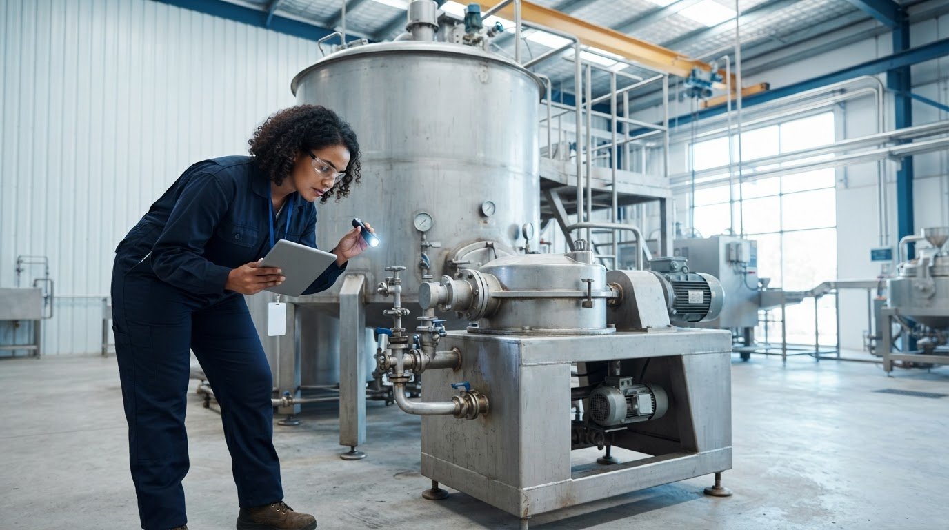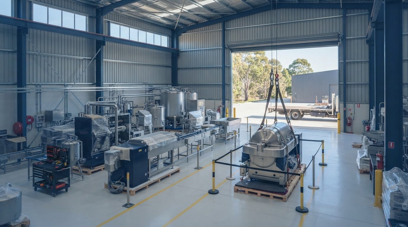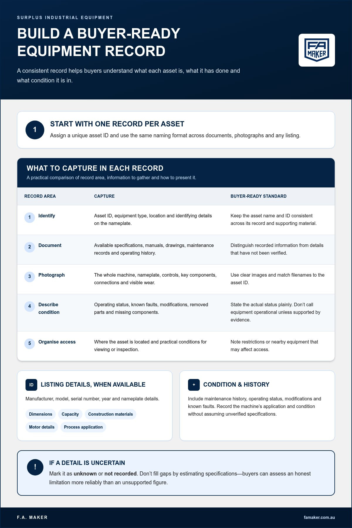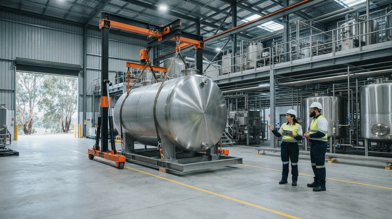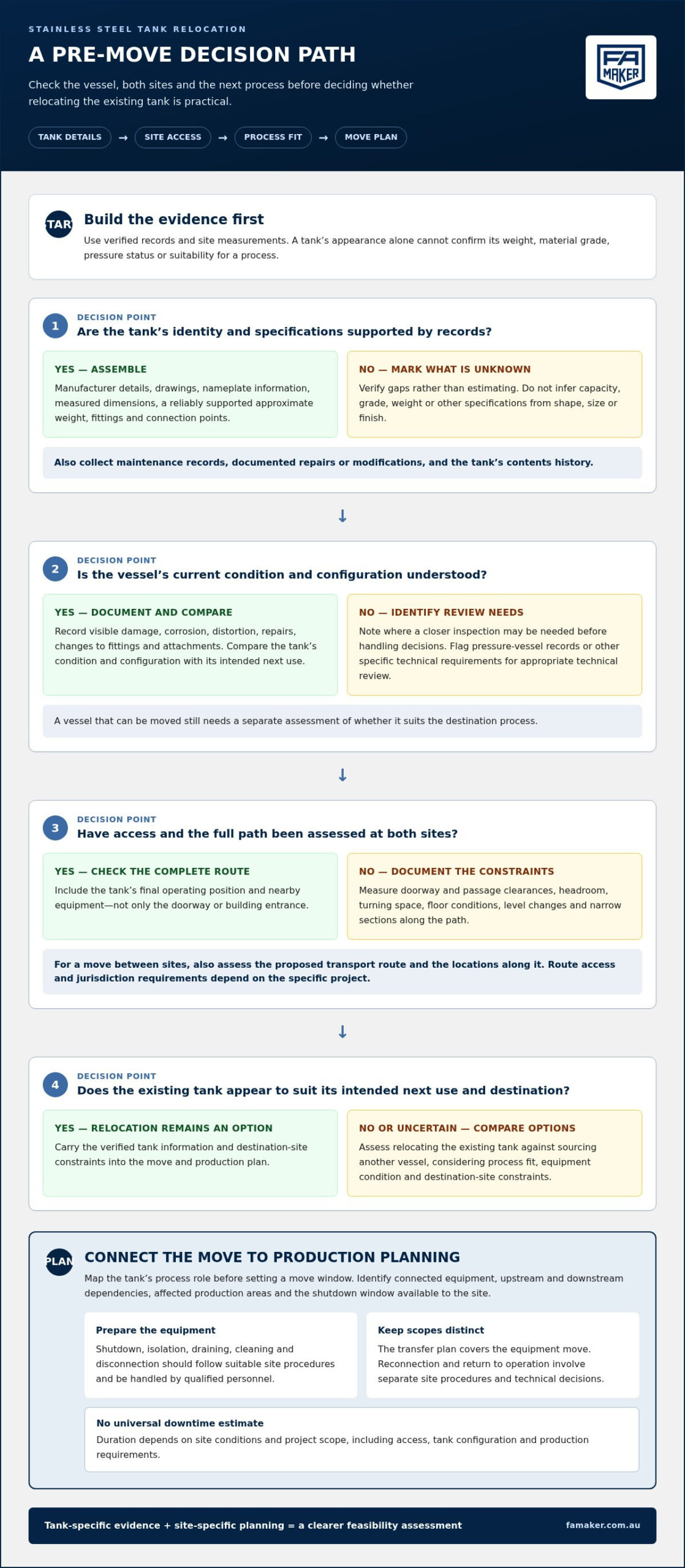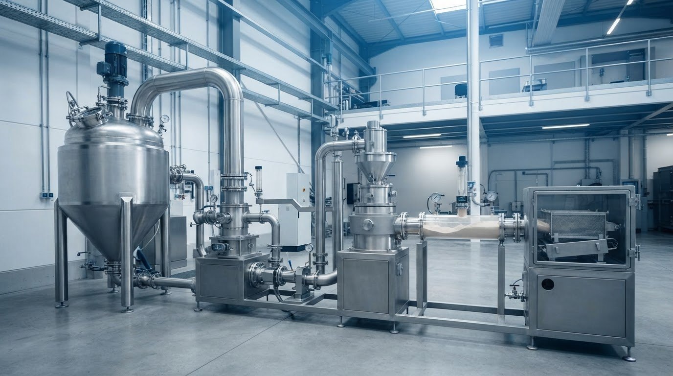
Equipment choices for consistent particle size at higher throughput

Higher throughput does not have to mean a wider particle-size distribution. The right equipment for scaling up production helps control the variables that affect particle size, including screen configuration, impeller design, tip speed, feed rate, and material characteristics. Assess these together, then validate the process as it moves from laboratory or pilot scale to production.

Choosing a larger machine based on capacity alone can overlook how the material responds to changes in mixing, milling, and flow. Consistency depends on the whole process: how equipment works together and whether the site can support the required layout and operation.

This article explains how to assess production systems and resources before expansion, compare equipment and mixer options, and evaluate flow components and space requirements. Use this framework to identify constraints, preserve process knowledge, and plan a scale-up that meets your throughput target and product requirements.

Key Takeaways

  • Map equipment, labour, materials and site constraints before increasing output so bottlenecks are visible early.
  • Compare production equipment by how it handles the material and process, not capacity alone; preserve relevant process conditions when moving from pilot to production.
  • Assess vessels, hoses, pipes and pumps as part of the full process line, since transfer and feed conditions can affect reliable operation.
  • Choose in-tank or in-line mixing based on the product, process requirements and how the mixer integrates with the production system.
  • Plan the layout around equipment, material movement, access and trained operators to support higher throughput without compromising consistency.

1. Evaluating systems and resources for expansion

Start by mapping the process from incoming materials to finished product. Record each operation, its current constraints, and where particle size is measured. For example, a milling line may meet its target until the feed rate rises, then produce a wider distribution. This baseline helps locate the constraint: in the mill, material feed, or a later process.

Consider scalability during concept development and manage it through new product introduction. For an existing line, compare current demand with realistic forecasts, then assess whether equipment, labour, materials, storage, and logistics can support the required production scale. Moving from laboratory or pilot scale to commercial production requires validation at each stage, not just a larger machine.

What production equipment is best for small and medium-sized Australian manufacturers? There is no single best machine. The right choice depends on the product, process, required output, and particle-size target. Match equipment to those conditions, then assess how it fits existing operations and available space.

Optimise the process before adding capacity. Review changeover time, cleaning, scheduling, material handling, and recurring bottlenecks. If a mixer sits idle while staff wait for material transfer, improving the transfer sequence may free capacity without replacing the mixer. Document standard operating procedures so each shift follows the same sequence and settings, helping maintain product quality as output increases.

Managing resources means planning people and supply alongside machinery. Identify which operators need training, whether maintenance tasks compete with production time, and whether suppliers can support higher material volumes. Material requirements planning, economic order quantity, and just-in-time inventory are approaches for managing stock; the suitable method depends on demand patterns and supply reliability. Keep at least 3-6 months of working capital to absorb increased operational costs when preparing to scale.

What Australian safety standards and regulations apply to production equipment? Requirements depend on the equipment hazards, workplace, and state or territory. Assess risks such as moving parts, cleaning access, and isolation during maintenance, then apply the relevant workplace safety requirements to the installation.

What permits, electrical requirements, or workplace approvals are needed to install production equipment in Australia? Before installation, assess the site’s electrical capacity, equipment connections, floor loading, access, and any effect on the building layout. Planning or building approvals and electrical work requirements depend on the site and proposed changes.

What are the installation, maintenance, training, and operating costs of production equipment? Build an estimate that includes installation work, utilities, consumables, planned maintenance, operator training, and downtime. Key cost drivers include equipment complexity, site modifications, operating hours, and the maintenance regime.

What risks should I consider when automating or expanding production? Poor planning can divert resources from other lines, delay deliveries, increase cash burn, or affect quality. Also assess staff training, supply-chain capacity, and the risk of producing stock that demand cannot absorb.

2. Evaluating equipment before capital investment

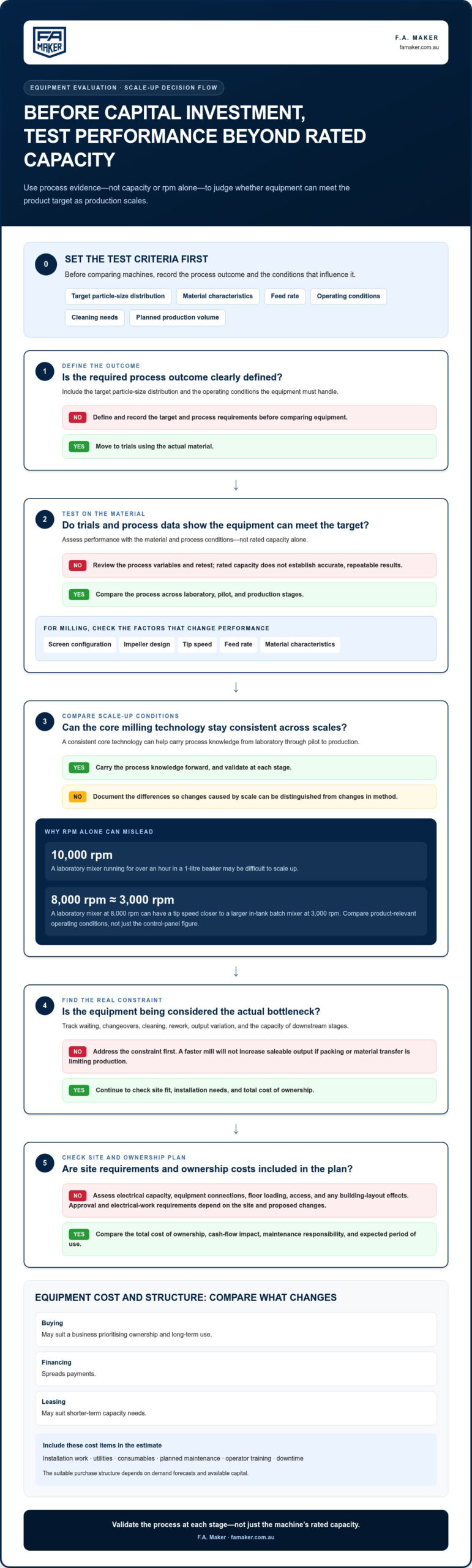
Before committing capital, define the process outcome the equipment must achieve. Record the target particle-size distribution, material characteristics, feed rate, operating conditions, cleaning needs, and planned production volume. Compare those requirements with equipment performance at laboratory, pilot, and production stages. Rated capacity alone does not show whether a machine can deliver accurate, repeatable results.

Use trials and process data to test how equipment handles the actual material. Milling performance can change with screen configuration, impeller design, tip speed, feed rate, and material characteristics. Where practical, keep the core milling technology consistent from laboratory through pilot and production stages. This helps teams carry process knowledge forward and identify differences caused by scale rather than a changed method.

A laboratory mixer running at 10,000 rpm for over an hour in a 1-litre beaker may be difficult to scale up. Rotational speed alone can mislead: a laboratory mixer running at 8,000 rpm can have a tip speed closer to a larger in-tank batch mixer running at 3,000 rpm. Compare the operating conditions that affect the product, not just the figures displayed on the control panel.

Should I buy, lease, or finance production equipment in Australia? Compare the total cost of ownership, cash-flow impact, maintenance responsibility, and expected period of use. Buying suits businesses that prioritise ownership and long-term use; financing spreads payments, while leasing may suit shorter-term capacity needs. The right structure depends on demand forecasts and available capital.

How do I identify production bottlenecks before buying equipment? Track each production stage, including waiting, changeovers, cleaning, rework, and output variation. Compare the time required at each stage with downstream capacity. A faster mill will not increase saleable output if packing or material transfer remains the constraint. Record particle-size results alongside operating conditions to locate quality losses.

Before upgrading machinery, prepare a process plan, timeline, budget, and obstacle register. Include installation work, staff training, maintenance access, utilities, and production interruptions. Research the machinery and identify safety hazards, including moving parts and cleaning access. These checks help uncover costs and risks beyond the purchase decision.

What Australian grants or tax incentives are available for manufacturing equipment investment? Eligibility depends on current Australian, state, or territory programs and their rules for business size, equipment use, and project purpose. Assess eligible support separately from the investment case, and base the production decision on demand, operating requirements, and product quality.

For process-specific planning, compare equipment requirements with the product and production method; for example, dairy processing equipment must fit the intended process and throughput.

3. Ancillary vessels, hoses, pipes and pumps

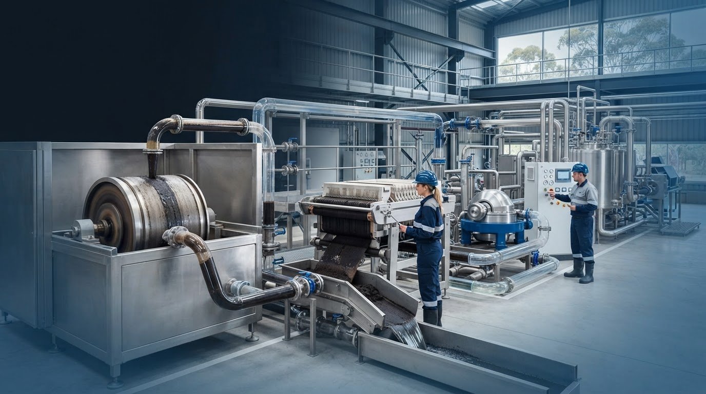
A production line can lose consistency between its main machine and supporting equipment. Trace the material path from the source vessel through each hose, pipe, pump, and receiving vessel. Mark every transfer, change of direction, hold point, and return line. This map can reveal where material may settle, separate, warm, cool, or remain trapped.

Start with the vessel’s role in the process. A feed vessel must supply the machine steadily, while a receiving vessel must accept the batch without interrupting discharge. Compare usable volume with batch size, headspace needs, agitation requirements, and transfer timing. For example, if the receiving vessel is still occupied at the next discharge, the line may have to pause even when the main machine has spare capacity.

Choose pumps based on the material and transfer duty. Review viscosity, solids content, sensitivity to shear, required flow, suction conditions, and discharge pressure. A pump that handles a thin liquid may not suit a viscous mixture or particle-containing slurry. Excessive shear may alter a sensitive product, while inadequate flow can lengthen transfer and disrupt the next operation. Match the pump to the full duty, not just the connection size.

Hoses and pipes also affect how reliably a line handles increased volumes. Check internal diameter, length, bends, elevation changes, connection points, and the route operators use for cleaning or changeovers. A narrow or sharply routed section can restrict flow, while a long line can increase retained product and cleaning demands. Keep connections accessible, support pipework appropriately, and avoid unnecessary branches where material can collect.

Set a transfer sequence operators can repeat. Document which vessel feeds each machine, the pump settings for the material, and the order for opening and closing valves. Include checks for leaks, blockages, unusual vibration, and incomplete drainage in routine inspections. Records of transfer time and batch variation can help distinguish a pump problem from inconsistent upstream mixing.

For a line handling multiple products, assess compatibility and changeover requirements. A hose suited to one product may need different cleaning or handling for another. Identify dedicated and shared lines, then specify how operators will prevent mix-ups. Confirm that every vessel, valve, and pump can be isolated for maintenance without creating an uncontrolled product route.

Finally, test the complete transfer path under representative operating conditions. Observe machine feed and discharge, check whether material remains at low points, and compare product samples before and after transfer. This system-level assessment helps determine whether additional pumps and valves or revised pipework will support the intended throughput and particle-size consistency.
Equipment choices for consistent particle size at higher throughput

4. Choosing in-tank or in-line mixers

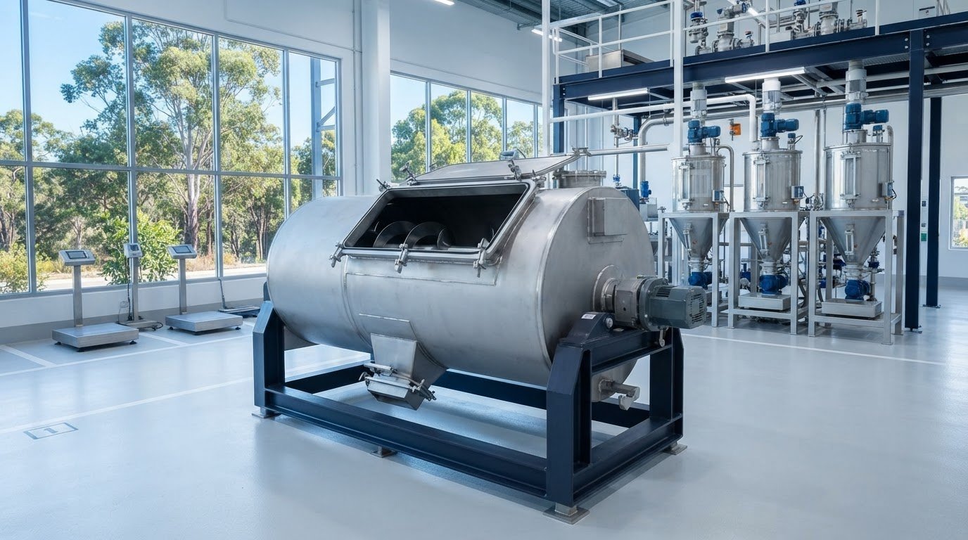
An in-tank mixer works inside a vessel, while an in-line mixer processes material as it passes through a pipe. The choice affects batch handling, production flow, cleaning, and operator control. Compare both arrangements with the process sequence, not just the mixer’s rated capacity.

For batch production, an in-tank mixer can suit processes that require a defined mixing period before discharge. Vessel geometry, fill level, impeller design, and material properties all influence circulation and mixing. For example, a partly filled vessel may not develop the same flow pattern as a full production batch. Document the working volume and mixing sequence for each product.

An in-line mixer can suit a continuous process or a line that feeds material directly between operations. It can reduce reliance on a separate mixing stage, but needs a suitable feed and stable flow through the mixing head. Review pump performance, pipework, pressure, and downstream capacity together. If flow varies, the mixer’s operating conditions can vary too.

Particle-size consistency depends on how the material responds to mixing. Agitation, shear, temperature, viscosity, and addition order can affect dispersion or agglomeration. Establish a repeatable test using the same material, feed conditions, mixing sequence, and particle-size measurement method. Compare samples taken at consistent process points, such as after mixing and after transfer.

For a scale-up, record impeller type, rotational speed, tip speed, vessel geometry, batch volume, and processing time. Most larger in-tank batch mixers run at a standard speed of 3,000 rpm. That figure alone doesn’t establish equivalent performance: impeller design, material behaviour, and vessel conditions also matter. Use pilot trials to identify which operating conditions must remain controlled as volume increases.

Use this decision sequence to narrow the configuration:

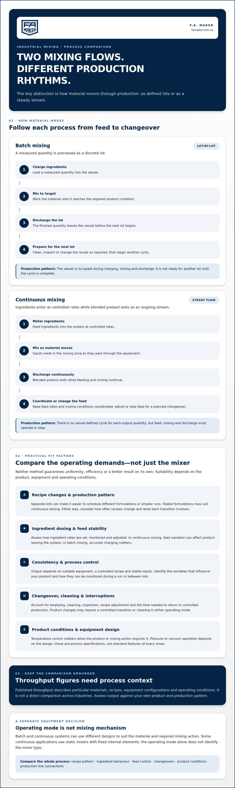
  1. Define the process. Identify whether production runs by batch, continuously, or through a combination of both.
  2. Characterise the material. Record viscosity, solids, temperature sensitivity, and the required particle-size distribution.
  3. Map the line. Include feed vessels, pumps, pipework, discharge, and the next operation.
  4. Validate performance. Compare mixing results and product samples under representative production conditions.

Cleaning and changeovers matter too. An in-tank configuration may require vessel access, while an in-line arrangement requires cleaning the mixer head and connected pipework. Consider product residues, inspection access, and the changeover sequence. For example, a line making several formulations needs a clear method to prevent carryover between batches.

Choose industrial mixers and blenders by matching the arrangement to material behaviour, process flow, and the consistency target. The right configuration must support both the required throughput and repeatable product quality.

5. Equipment and space requirements

To scale up, plan the entire production route, not just the main machine. List each operation from material receipt through processing, holding, packing, and dispatch. Include vessels, mixers, pumps, conveyors, controls, and cleaning access where relevant. A line may have enough processing capacity yet remain constrained by storage, transfer, or packing space.

What equipment is needed to scale up production? It depends on the process and target output, but typically includes the core processing machine, suitable feed and receiving vessels, pumps, controls, and downstream handling equipment. Add components only to remove a verified constraint or meet a defined production requirement.

Calculate required throughput from the saleable output needed during available production time. Account for batch preparation, processing, discharge, cleaning, changeovers, and planned maintenance. Then compare each operation’s usable capacity with that requirement. If a mill feeds a packaging line, for example, the line’s sustainable rate must accommodate the mill’s output without creating a queue or disrupting product handling.

For a batch process, calculate working volume and cycle sequence, including loading and discharge. For continuous production, map material flow through each stage and identify where it waits. Compare required output with demonstrated operating performance, then investigate the bottleneck before adding equipment. Name the constraint clearly, such as insufficient holding capacity or a slow transfer step.

What equipment is needed also depends on product and process. A 100 mL flask and a 100 L reactor represent different scales in a small-molecule scale-up example; the larger vessel doesn’t automatically reproduce the same conditions. Likewise, doubling production may require double the equipment, space, and trained staff. Treat that as a planning possibility, then assess the actual process, layout, and operating model.

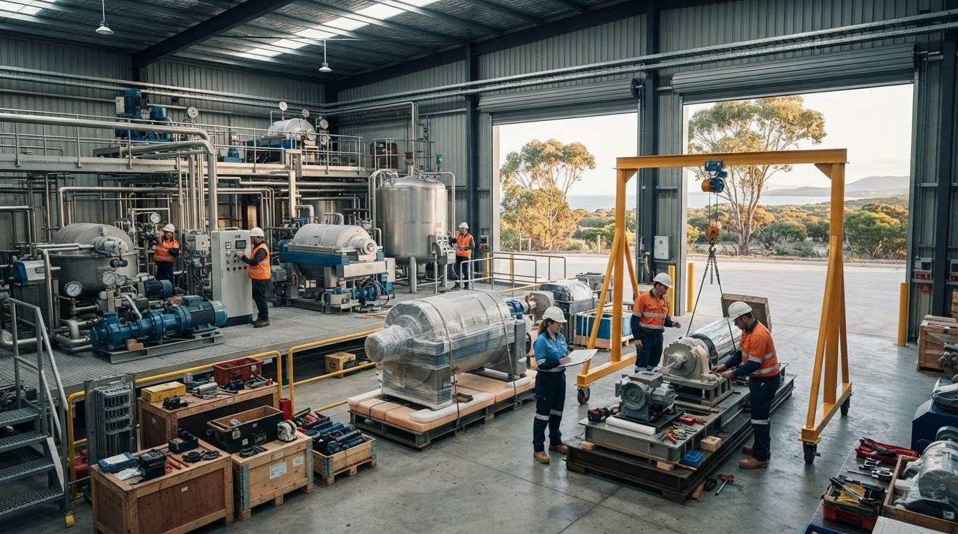
Mark proposed equipment footprints on the site plan, including operator access, material routes, maintenance clearance, and cleaning areas. Check doorways and travel paths for delivery and installation. Allow space for connected vessels and pipework, not just the machine frame. In an Australian facility, also assess how the proposed layout affects existing operations and safe access.

Protect consistency as the production footprint grows. Keep raw materials, work in progress, finished product, and waste routes distinct in the layout. Identify where operators sample material and record results, then preserve those control points in the expanded line. If the new equipment changes transfer distance or storage time, include those changes in process validation.

For a filling-line capacity requirement, review bottle filler options alongside the upstream process and available floor space. A layout strategy that accounts for the filler, feed supply, access, and product flow supports a more practical scale-up plan.

F.A. Maker: Used Stainless Steel Tanks

F.A. Maker supplies used stainless steel tanks for manufacturers assessing additional process or holding capacity during expansion. Turn to F.A. Maker when your process plan identifies a need for another vessel or supporting equipment alongside the main production machine.

The range also includes industrial mixers and blenders, centrifuges and separators, and pumps and valves. These categories support different production stages, from mixing and separation to material transfer. Match the equipment’s function to your process, product, and layout before selecting a machine.

Contact F.A. Maker to discuss your production equipment requirements and how a tank or other listed equipment could support your expansion.

Turn your scale-up plan into an equipment decision

Next, turn your production targets into a practical equipment brief. Define product requirements, intended operating conditions, and the constraints the proposed setup must address. This gives your team a clear basis for comparing options and planning the transition, without treating higher throughput as the only measure of success.

For Australian manufacturers reviewing process equipment, F.A. Maker offers used stainless steel tanks, centrifuges and separators, and industrial mixers and blenders. These can suit different stages of a production line, depending on the process and each machine’s role. The right equipment for scaling up production should fit the wider system, not just one operation.

Share your process requirements and equipment priorities with F.A. Maker as you develop the next stage of your plan. Contact F.A. Maker to discuss your needs and take a considered next step towards greater production capacity.

Frequently Asked Questions

How do you keep particle size distribution consistent while increasing the throughput of your operations?

Increase throughput in controlled stages, comparing particle-size results with a defined product specification. Take representative samples at consistent points, such as before and after milling, and record operating conditions for each batch. When selecting equipment for scaling up production, account for feed characteristics and the effects of changes to feed rate, screen configuration, and mill settings. Investigate variation before increasing output further.

What does it mean to scale up in manufacturing?

Scaling up in manufacturing means transferring a process from laboratory or pilot scale to a larger pilot or production scale while aiming to maintain the required output and quality. The larger system can change how material moves, mixes, heats, or cools. For example, a process instruction that works for a small trial may need revised feed sequencing or monitoring at production scale. Scale-up is a process change, not simply buying a larger machine.

What equipment options can best help to support seamless milling scale-up from lab to production?

Where practical, use the same core milling technology from laboratory through pilot and production stages, then validate it with representative material. Hammer mills and pin mills are equipment options; the right choice depends on the product and desired particle-size distribution. Compare screen configuration, feed method, and operating conditions between stages. Pilot validation helps operators establish a workable process before commercial production, without assuming similarly named mills produce identical results.

Why is it often so challenging to scale up size reduction equipment from lab to production?

Size reduction is challenging to scale because a larger machine changes the interaction between material, moving components, and process conditions. Material feed, screen configuration, impeller design, and tip speed can all affect particle-size distribution. A laboratory setup may also handle material differently from a production line with continuous feed and longer transfers. Comparing test results across stages helps identify which process variables need adjustment before production runs begin.

How do I integrate new equipment with existing production lines and software?

Map the production process and material path, then check the new equipment’s operating requirements, transfer points, utilities, layout, and fit with existing operations. Document standard procedures, and use an ERP system to connect inventory, production scheduling, financials, and purchasing.
Double Cone Blender vs V-Blender: Which Should You Choose

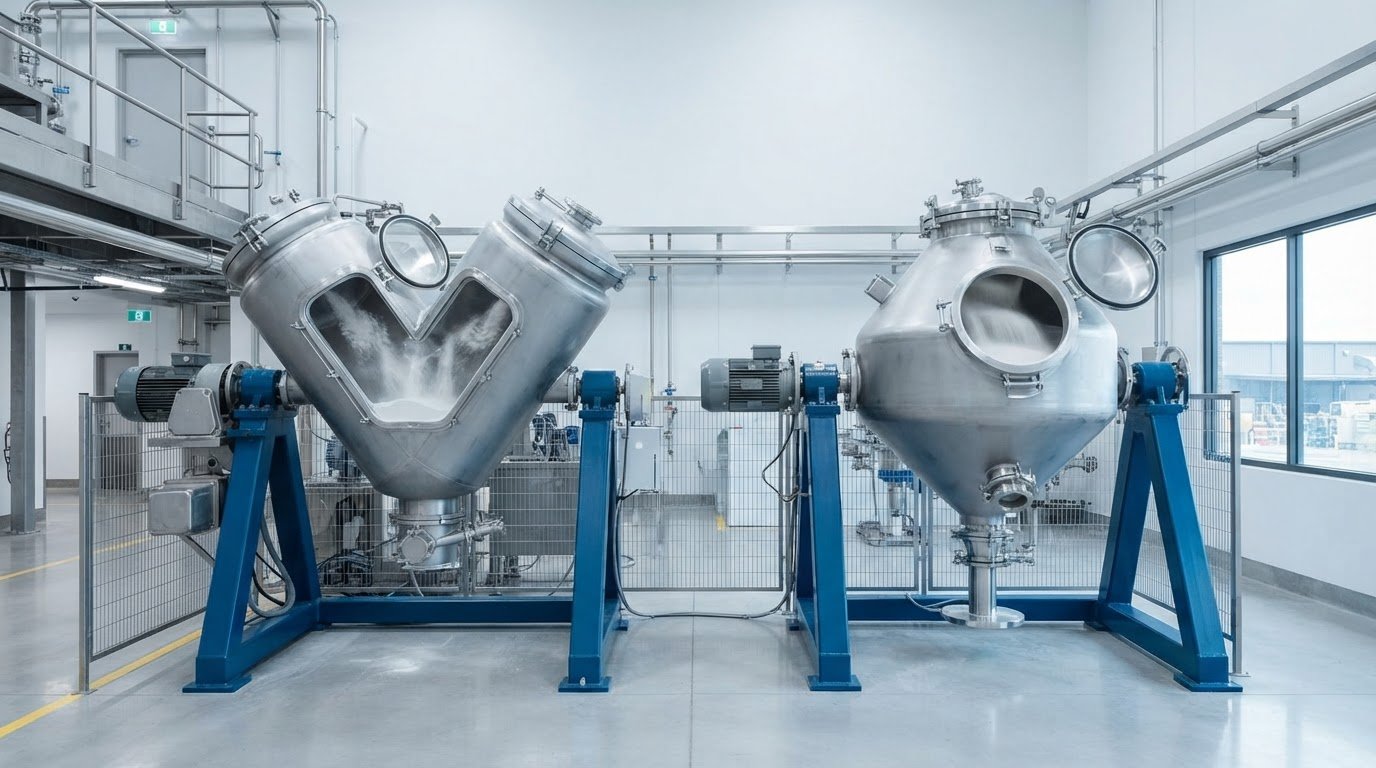
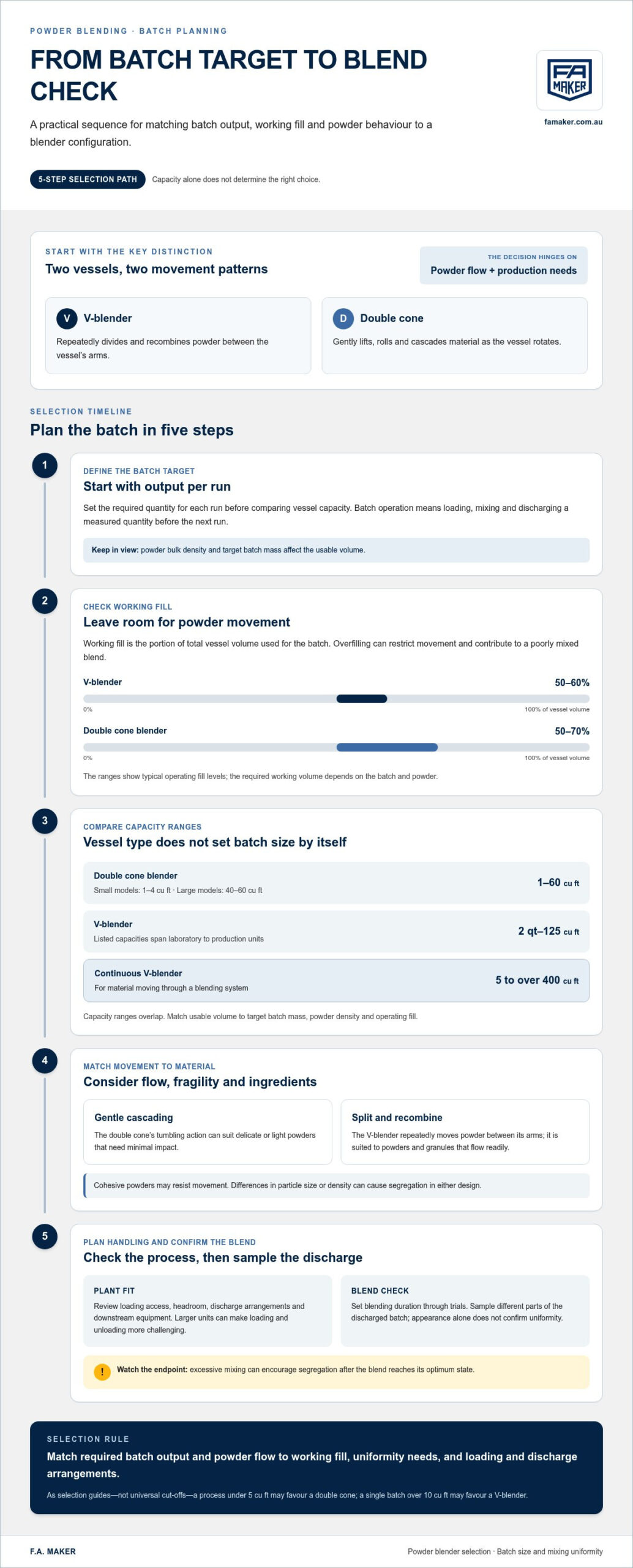
The more complex-looking blender isn’t automatically the better choice. In the double cone blender vs V-blender comparison, the deciding factor is how each vessel moves the powder: a V-blender repeatedly separates and recombines material, while a double cone blender gently lifts and cascades it. A V-blender is typically filled to 50-60% of its total volume, compared with 50%-70% for a double cone blender.

Both designs use tumbling motion, but their differences go beyond the shape of the machine. Material flow, batch size, required uniformity, and loading and discharge arrangements all matter when choosing equipment for an Australian processing operation. This comparison explains how each design works, how its mixing action affects powder behaviour, and what to consider when assessing blending time and handling. Use it to decide which configuration better suits your material and production requirements.

Key Takeaways

  • Choose a blender by matching its mixing action to the powder’s flow, fragility and ingredient characteristics.
  • Assess working batch volume, not just vessel capacity, to avoid loading conditions that restrict powder movement.
  • Compare access, headroom and discharge arrangements with your plant layout and material-handling process.
  • Set blending duration through trials and assess uniformity at discharge, since excessive mixing can encourage segregation.
  • Use the decision guide to weigh production scale, handling needs and the level of blend uniformity required.

Batch size and mixing uniformity

Vessel capacity and working batch size are different measures. A V-blender is generally operated at a fill level of 50-60% of total vessel volume, leaving space for powder to move between its arms. Overfilling can restrict that movement and produce a poorly mixed blend. A double cone blender is usually filled to 50%-70% of its volume, allowing the material to tumble as the vessel rotates.

Typical double cone blender capacities range from 1 to 60 cubic feet. Small models commonly hold 1-4 cubic feet, while large models typically hold 40-60 cubic feet. V-blenders span laboratory models to production units, with listed capacities from 2 qt to 125 cu ft. Those ranges overlap, so vessel type alone doesn’t determine batch size. Powder density, target batch mass and the required operating fill all affect the usable volume.

Uniformity depends on movement, not capacity alone. A V-blender repeatedly divides and recombines flowing powder, while a double cone blender lifts and cascades it. Both actions can produce a homogeneous mixture when ingredients flow freely. Differences in particle size or density can still lead to segregation in either design. For a new formulation, sample different parts of the discharged batch rather than judging uniformity by appearance alone.

Batch operation suits production that needs a measured quantity of ingredients loaded, mixed and discharged before the next run. Continuous V-blender configurations are also described, with capacities from 5 cubic feet to over 400 cubic feet. Continuous equipment serves a different process requirement: material moves through the blending system rather than being handled as one discrete batch. Match the operating mode to the production flow and downstream equipment.

Custom batch sizing starts with the required output per run, then accounts for the blender’s working fill and the powder’s bulk density. For example, a small-batch process under 5 cubic feet may favour a double cone blender, while a single batch over 10 cubic feet may favour a V-blender. These are selection guides, not universal cut-offs. A V-blender may be less practical at very small or very large batch sizes, and larger units can make loading and unloading more challenging.

Option Typical capacity Working fill Batch considerations
Double cone blender 1-60 cubic feet 50%-70% Broad batch range; straightforward loading and unloading
V-blender 2 qt-125 cu ft 50-60% Allow space for powder movement; large units may be harder to handle
Continuous V-blender 5 to over 400 cubic feet Process-dependent Consider for continuous material flow

Choose a blender by matching the required batch output and powder flow with the working fill, uniformity requirements, and loading and discharge arrangements.

V Cone Blender and Double Cone Blender: What Makes Them Different?

In Australia, assess industrial powder blenders against workplace safety controls and process hygiene requirements, including guarding, dust management, and cleanability. Uneven flow, differences in particle size or density, or excessive mixing can lead to poor blending or segregation.

Double-Cone Configuration and Tumbling Action

A double cone blender has two cone-shaped chambers joined at their wide ends and rotates around a central shaft. As the vessel turns, powders roll, drop, and move between the cones. This tumbling action relies on gravity, rather than the V-blender’s repeated split-and-recombine movement. The open cone geometry provides gentle mixing, which can suit fragile materials that need minimal impact during operation.

V-Cone Shape and Mixing Action

A V-blender uses two cylindrical sections joined at an angle to form a V-shaped vessel. During rotation, the vessel divides powders between its arms, then brings them together again. This repeated separation and recombination creates a different movement pattern from the double cone’s cascading action. The V-shaped chamber uses gravity without internal agitators, making it suited to powders and granules that flow readily.

Blending Action and Product Fragility

The key difference is how material travels through each vessel. A double cone lifts and cascades the mixture, providing gentle tumbling for delicate or light powders. A V-blender repeatedly divides and recombines ingredients, promoting movement between its arms. Both designs can handle fragile substances, but material behaviour matters: free-flowing particles move more readily, while cohesive powders can resist uniform movement. Match the vessel’s action to the product’s fragility and flow characteristics.

Mixing and Segregation Risks

Neither vessel shape prevents segregation on its own. Powders with different particle sizes or densities may separate during mixing or after discharge, even when the initial blend looks homogeneous. In a V-blender, cohesive material may not move effectively between the arms; in either design, poor flow can leave parts of the mixture unevenly blended. Assess ingredient characteristics and sample the finished blend to evaluate uniformity. Excessive mixing can also increase segregation after the blend reaches its optimum state.

For Australian processing operations comparing vessel designs, review industrial mixing equipment alongside the material’s movement and handling requirements.

Double cone blender design and operation

A double cone blender has two cone-shaped sections joined at their wide ends, forming a chamber that rotates on a central shaft. Its tapered ends guide powder towards the centre and back as the vessel turns. This compact arrangement supports gentle handling, and the interior has few corners or tight spaces. That geometry can simplify cleaning compared with a V-shaped chamber, where powder may collect at the arm junctions.

A V-blender consists of two cylindrical shells connected at an angle. Each arm has an access cover for loading, inspection, and cleaning. During operation, rotation carries the ingredients through the arms, with gravity driving their movement. The angled junction creates a distinct flow path, but also needs attention during cleaning. The design requires more headroom than a double cone blender, which can affect placement in a processing room.

Both designs suit free-flowing powders and granules. A V-blender can be efficient when repeated separation and recombination help distribute ingredients. A double cone blender is a practical option when gentle tumbling is a priority, including for fragile material. The better fit depends on flowability, sensitivity to handling, required uniformity, and batch size. Pharmaceutical powders, for example, can be processed in either design, depending on formulation needs.

Material behaviour helps distinguish the options beyond vessel geometry. V-blenders work effectively with free-flowing powders, but cohesion can hinder movement between the arms. They may also be less suitable when ingredients have substantial particle-size differences. Double cone blenders can handle free-flowing powders and materials with varying particle sizes; their tumbling action also suits delicate products. Sticky or wet materials can adhere to a double cone’s inner walls and mix poorly, so compatibility with dry materials remains a key selection point.

Plan operation around access and cleaning as well as the mixing cycle. A V-blender’s separate arm covers provide access for inspection and cleaning, though its junctions need careful attention. A double cone blender’s single access cover provides a straightforward entry point, and its smooth interior can reduce hard-to-reach areas. Confirm that the blender’s position allows safe loading, inspection, and discharge within the plant layout. For a pharmaceutical formulation, assess powder flow and fragility before choosing a vessel, then evaluate the resulting blend for uniformity.

In practical terms, choose a V-blender when free-flowing ingredients benefit from movement between two arms. Choose a double cone blender when gentle tumbling, accessible cleaning, or varied particle sizes matter more. The vessel should suit both the material and the way operators will load, inspect, and clean it.

Double Cone Blender vs V-Blender: Which Should You Choose

Loading, rotation, blending duration and discharge

Both designs use rotation to move powder, but their operating times vary with material and batch size. V-blender batches can take from 5 minutes to over an hour; a typical V-Cone batch reaches target homogeneity in 5 to 15 minutes. Double cone mixing can take several minutes to over an hour. Uniformity depends on the formulation and mixing conditions, not simply the machine’s rotation time.

Load ingredients in their required proportions before starting either machine. A double cone blender is usually filled to 50%-70% of total volume, while a V-blender’s optimal fill is 50-60%. These working levels leave room for powder movement. Overfilling a V-blender can prevent material from travelling between its arms, impairing the blend. During loading, an even distribution of ingredients supports the intended mixing action.

Rotation speed and blending time can be adjusted to achieve the required homogeneity. V-blender speeds vary from 5 to 40 RPM, depending on the application. Use the material’s flow behaviour and blend uniformity as process considerations, rather than assuming that a longer cycle improves results. Excessive mixing can increase segregation after the powder reaches its optimum blend state. Establish the cycle through testing and assess samples at discharge.

Blending-stage descriptions distinguish the designs: V-blenders use a single blending stage, while double cone blenders use two. After blending, material exits from the bottom of the vessel. V-blenders have bottom discharge valves, and double cone blenders also discharge through a bottom outlet. Plan the receiving container or downstream equipment around the outlet position, especially when the mixture feeds a chemical process or bottle-filling line.

Cleaning and changeover involve different access points. A double cone blender has one access cover, and its interior has few corners or tight spots. This shape can make inspection and cleaning more straightforward. Each V-blender arm has its own access cover for loading, inspection, and cleaning. Powder can collect where the arms join, so pay particular attention to that junction during cleaning to reduce residue and contamination between applications.

For a controlled changeover, discharge the batch fully, inspect accessible surfaces, then clean the vessel and outlet before loading the next ingredients. Pay particular attention to the V-blender’s junction and discharge valves; the double cone’s cover and bottom outlet are key inspection points. Record the selected speed, cycle duration, and discharge sampling results for each formulation. These operating records help reproduce a uniform mixture in later batches.

Double cone and V-blender mixing motion

A double cone blender gently cascades material through its rotating vessel; a V-blender repeatedly divides and recombines it. This difference in motion affects powder flow, the handling of delicate ingredients, and how operators assess a formulation.

Double-Cone Mixing Motion

As a double cone rotates, powder lifts along the vessel wall before falling towards its centre. Each turn shifts material between the two conical ends, creating gentle tumbling rather than a sharp split between separate arms. This movement can suit fragile products that need limited impact. For example, delicate granules may benefit from gradual cascading rather than repeated division and recombination.

V-Blender Mixing Motion

A V-blender’s two arms repeatedly separate and recombine the powder as the vessel rotates. This creates intersecting movement paths through the ingredients, supporting distribution when particles flow freely. V-blender agitator speeds vary from 5 to 40 RPM, depending on the application. Unlike the double cone’s cascading path, the V shape makes the split-and-combine action central to its mixing operation.

Neither motion guarantees a consistent blend for every formulation. Particle size, density, and flow behaviour influence how ingredients travel through the vessel. Free-flowing powder can move between V-blender arms, while cohesive material may resist that movement. In a double cone, powder must cascade readily to circulate between the ends. Material that moves poorly can leave uneven concentrations in either machine.

Mixing intensity also matters for fragile materials. A double cone’s gentle tumbling can help limit impact on delicate granules, while a V-blender’s repeated division creates a different pattern of particle movement. Both designs are used in pharmaceutical, chemical, and nutraceutical industries. To assess a formulation, compare samples from different discharge points and check whether the mixture achieves the required uniformity. Excessive mixing can encourage segregation after the optimum blend state.

The practical takeaway is to match motion to material: choose cascading for gentle handling, or split-and-recombine movement for free-flowing ingredients. The V-blender’s movement pattern is not automatically more efficient; flow characteristics determine whether it can distribute each ingredient consistently. To compare equipment suited to your process, review industrial mixers and blenders.

A V-blender uses two connected cylinders to divide and recombine particle movement during blending. Its connected form defines the route that material follows, while the double cone uses a different path: materials cascade between its cones as the central shaft rotates. These features distinguish the vessels by how they direct movement, rather than treating their mixing actions as identical.

Both double cone blenders and V-blenders split their contents each time the vessel is inverted. Their rotation speed can be adjusted so contents slide towards the lower part of the vessel during rotation. Considering vessel shape alongside this adjustable movement helps clarify which blending action suits a material.

F.A. Maker: Used Stainless Steel Tanks

F.A. Maker supplies industrial mixers and blenders for processing operations comparing double cone and V-blender designs. The choice depends on powder flow, fragility, batch requirements, and how the equipment fits the wider production line. Consider the blender alongside related process equipment, such as stainless steel tanks for storage or pumps and valves for material transfer. F.A. Maker also offers centrifuges and separators for other separation stages in processing.

Turn to F.A. Maker when sourcing used stainless steel tanks or industrial processing equipment to support your operation. The range can help you assess equipment needs across connected process stages, without treating the blender as an isolated purchase. Visit famaker.com.au to discuss your equipment requirements.

Move From Blender Selection to Process Planning

Use the double cone blender vs V-blender comparison as a starting point for a broader process review. Define the product-handling requirements, production workflow, and equipment connections that will shape your purchase decision. A blender must fit its place in the line, from ingredient preparation through to storage and separation.

F.A. Maker offers Industrial Mixers and Blenders, Used Stainless Steel Tanks, and Centrifuges and Separators. Consider these equipment categories alongside your blending requirements when planning or updating a processing operation. The next step is to outline the material and workflow needs for your application.

Contact F.A. Maker about your blending needs and take the next step with a clear equipment plan.

Frequently Asked Questions

What Are the Advantages of a V Blender?

A V-blender’s repeated division and recombination can distribute free-flowing ingredients effectively. Its gravity-driven action uses no internal agitators, keeping the mixing mechanism straightforward. This can suit dry formulations that need repeated redistribution through the vessel. For example, a process combining several free-flowing powder components can benefit from movement through both arms. Performance still depends on how readily each ingredient flows.

What are the Disadvantages of V Blenders?

V-blenders can struggle when cohesive powders do not move readily between the arms. Differences in particle size or density can also contribute to segregation, even after blending. An unsuitable fill level can restrict the movement needed for mixing. The arm junction may need extra attention during cleaning, and larger machines can be more challenging to load and unload. Consider these constraints when assessing a formulation and its production workflow.

What are the key differences in mixing performance between double cone and V-blenders?

The main performance difference is powder movement: a double cone tumbles and cascades material, while a V-blender repeatedly separates and recombines it. The best fit depends on how the formulation responds to each motion. Compare trial blends using samples from several discharge points, then assess ingredient distribution. This practical test helps determine whether the selected machine achieves consistent results for the powder combination.

What are the typical capacity ranges and batch sizes for each blender type?

Double cone blender capacities are listed from 2 qt to 100 cu ft, with typical models ranging from 1 to 60 cubic feet. V-blender capacities range from 2 qt bench-top configurations to 125 cu ft. These are vessel capacity ranges, not guaranteed working batch volumes. Account for the required fill level and powder bulk density when translating vessel volume into a production batch quantity.

What are the advantages and disadvantages of each blender for pharmaceutical and food production?

Both designs are used in pharmaceutical and food production, with selection guided by formulation flow, fragility, and batch needs. A double cone’s gentle tumbling can suit delicate powders, while a V-blender’s movement can work well with free-flowing ingredients. Cohesive material may move poorly in a V-blender; wet or sticky material can adhere inside a double cone. Assess product handling and cleanability for each process.

Determining fair market value for used machinery and its price

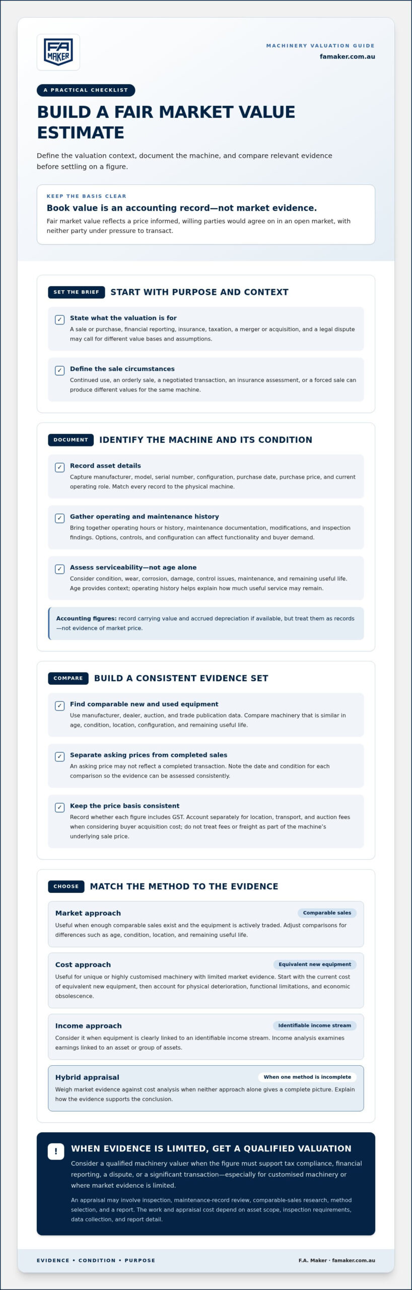
A machine’s book value is not necessarily its fair market value. In Australia, determining fair market value for used machinery means estimating the price informed, willing parties would agree on in an open market, with neither party under pressure to transact. The estimate typically starts with comparable machinery sales, then accounts for condition, age, demand and remaining useful life.

It’s reasonable to expect a clear figure, but the result depends on what value is being assessed and the assumptions behind it. A negotiated sale, an insurance assessment and a forced sale can produce different values for the same machine.

This article explains how the market, cost and income approaches work, when replacement cost is useful, and how fair value differs from other valuation bases. It also outlines the assumptions that shape an estimate, so you can understand how machinery value is determined and which factors matter most in your situation.

Key Takeaways

  • Choose a valuation approach that fits the machine and the available evidence: comparable sales, replacement cost, or income analysis may each play a role.
  • Assess condition, operating history, remaining useful life, market demand and obsolescence rather than relying on book value alone.
  • Income analysis is generally difficult to apply to an individual machine because its contribution to a business’s cash flow can be hard to isolate.
  • Replacement cost estimates what equivalent new equipment would cost, then accounts for depreciation and obsolescence.
  • Define the purpose and assumptions of the valuation first, since continued-use, orderly-sale and forced-sale values can differ.

What is Plant, Machinery and Equipment Valuation?

A plant, machinery and equipment valuation estimates an asset’s value for a defined purpose and under specific market conditions. The chosen approach affects the result, so it should suit the machine, the available evidence and the decision you need to make.

Valuation Approaches

A valuation approach provides a framework for estimating value from market evidence, replacement cost or expected income. The market approach compares similar machinery sales. The cost approach starts with equivalent new equipment and adjusts for depreciation and obsolescence. The income approach analyses earnings linked to an asset or group of assets. A hybrid appraisal can weigh market evidence against cost analysis when neither alone gives a complete picture.

For example, comparable sales may anchor the estimate for a standard pump, while replacement cost can help assess a customised processing line. Income analysis is more relevant when equipment is clearly linked to an identifiable income stream. Combining approaches shows how the evidence supports the conclusion, rather than presenting a single figure without context.

Purpose of Equipment Valuation

Plant, machinery and equipment valuation provides an independent estimate for a specific business or financial decision. It can support sales and purchases, financial reporting, insurance, taxation, mergers and acquisitions, and legal disputes. The purpose matters because the required value basis and assumptions can differ between a negotiated sale and an insurance assessment.

A valuation can also inform liquidation, sales negotiations and investment analysis. For Australian tax compliance, the methodology should suit industry practice, available data and market circumstances. A professional appraisal may involve inspecting equipment, reviewing maintenance records, gathering comparable sales data, selecting a method and preparing a report. Each step ties the estimate to the asset’s condition and intended use.

Choosing Cost or Market Methods

The market approach is generally useful when comparable machinery sales provide enough evidence to assess demand and likely transaction prices. It suits equipment that is actively traded. Comparisons should account for differences in age, condition, location and remaining useful life, because an asking price may not reflect a completed sale.

The cost approach is more useful for unique or highly customised machinery with limited market evidence. It starts with the current cost of equivalent new equipment, then accounts for physical deterioration, functional limitations and economic obsolescence. When market data is scarce, an appraiser can compare the cost-based result with available sales evidence and explain the weighting. The valuation’s purpose also guides the choice.

DIY Valuation and Market Research

A preliminary DIY assessment can help organise evidence before a sale or purchase discussion. Record the machine’s make, model, age, configuration, operating history, condition, maintenance documentation and modifications. Then compare similar new and used equipment using manufacturer, dealer, auction and trade publication data. Distinguish asking prices from completed sales, and note the date and condition of each comparison.

For comparable prices, keep the basis consistent. Record whether each figure includes GST, then account separately for location, transport and auction fees when assessing the buyer’s total acquisition cost. Don’t treat fees or freight as part of the machine’s underlying sale price.

Engage a qualified machinery valuer when the figure must support tax compliance, financial reporting, a dispute or a significant transaction, especially if the machinery is customised or market evidence is limited. Appraisal costs depend on the asset scope, inspection requirements, data collection and report detail; a quote should reflect that work.

How to determine the fair value of a machine?

Start by identifying the asset, its condition and the intended sale context, then compare relevant evidence. Fair market value reflects a price agreed by informed, willing parties who aren’t under pressure to transact.

Identifying Equipment and Compiling Asset Information

Asset identification records what the machine is and which characteristics distinguish it from comparable equipment. Capture its manufacturer, model, serial number, configuration, purchase date, purchase price and current operating role. Include the balance-sheet carrying value and accrued depreciation if available, but treat accounting figures as records, not market evidence.

Match each record to the physical machine before valuing it. A model designation alone may miss options, control systems or modifications that affect functionality and buyer demand. When determining fair market value for used machinery, organise maintenance records and operating history alongside inspection findings. This provides a consistent basis for comparison.

Age, Condition, Demand, and Functionality

Age provides context, but operating history and condition indicate how much useful service may remain. A lightly used standby generator can have a lower effective age than a newer machine with intensive operating hours. Inspect for wear, corrosion, damage, control issues and signs of maintenance. Missing records make it harder to distinguish a well-maintained machine from one with hidden deterioration.

Functionality and demand also influence saleability. Equipment that performs its intended process efficiently may attract more buyers than a machine requiring substantial modification. Technological obsolescence can reduce value even when equipment still operates, particularly if replacement parts or compatible controls are difficult to source. Compare the machine with assets of similar capacity and configuration, not just similar age.

Why the Income Approach Is Not Used

The income approach estimates value from future earnings, but those earnings can be difficult to isolate for an individual machine. A production line’s output may depend on several machines, labour, materials, maintenance and sales conditions. Assigning a precise share of business income to one asset can therefore produce an unsupported estimate.

For an individual asset, the market approach is generally more useful when comparable sale evidence exists. It tests the machine against actual market demand and similar transactions. Income analysis may be more relevant when equipment is clearly linked to a distinct income stream, but projected business revenue is not a direct measure of standalone equipment value.

Risks That Can Distort a Valuation

Liens, undisclosed defects and obsolete parts can distort an estimate if their effect on transferability, condition or buyer costs is overlooked. A lien may affect the seller’s ability to transfer an asset free of an encumbrance. Mechanical defects can reduce performance, while unavailable parts can increase downtime or repair requirements.

Check inspection findings against maintenance records and the machine’s stated configuration. Compare asking prices cautiously: listings may differ from completed transactions, and asking prices can be 10-15% higher than final prices. Record whether each comparison is an asking or sale price, and account separately for transport, location, GST and auction fees. For equipment purchases involving a move, planning machinery requirements can help connect valuation assumptions with operational needs.

Cost approach and replacement cost

The cost approach estimates machinery value from the cost of equivalent new equipment, adjusted for depreciation and obsolescence. It is especially useful when comparable sales are scarce, as with unique or highly customised assets.

Replacement Cost as a Valuation Basis

Replacement cost new is the current cost of buying a new asset that performs the same function as the existing machine. It need not be an identical model; the replacement must provide equivalent utility. This distinction matters when manufacturers have changed designs or discontinued older machinery.

Reproduction cost new instead estimates the current cost of constructing a duplicate. The distinction matters for specialised equipment: a functional equivalent may be easier to source than an exact replica. For reporting or transactions, the selected basis should match the valuation purpose and clearly state what is being replaced.

The cost approach adjusts the relevant new-equipment cost for physical deterioration, functional obsolescence and economic obsolescence. Physical deterioration reflects wear and damage. Functional obsolescence arises when design limits performance or efficiency. Economic obsolescence reflects external conditions that reduce the asset’s usefulness or demand. Each adjustment accounts for a different reason the used machine may be worth less than new equipment.

Depreciation in the Cost Method

In a cost-based valuation, depreciation represents lost utility, not simply an accounting charge. The estimate considers age, condition, maintenance, remaining useful life and obsolescence. A machine with wear concentrated in replaceable components may retain more utility than one with outdated controls or structural deterioration.

Actual cash value is replacement cost new minus depreciation based on the equipment’s remaining useful life. This measure can be relevant to insurance, although a policy may instead use replacement cost new or reproduction cost new. The applicable basis depends on the policy wording, so the report should identify the chosen definition rather than treat these terms as interchangeable.

Useful-life assessment should reflect the machine’s operating role and condition, not age alone. Maintenance records, inspection findings and known limitations help explain depreciation adjustments. If the machine has been upgraded, assess whether the upgrades restore function or merely postpone deterioration. This ties the estimate to current utility instead of assuming every year of age causes the same loss.

For a unique asset with little market evidence, the cost method offers a structured basis for analysis, but replacement cost is not automatically its sale price. Buyers may discount equipment that needs installation, has limited demand or cannot meet current production requirements. A sound valuation explains the replacement basis, each depreciation adjustment and the assumptions behind the result.

Determining fair market value for used machinery and its price

Fair market value and other value definitions

Equipment value depends on the valuation basis, intended use and transaction assumptions. Fair market value, market value and accounting fair value are related concepts, but they aren’t interchangeable. Naming the required basis helps buyers, sellers and finance teams understand what a reported figure represents.

Fair market value estimates the price an asset would bring between informed, willing parties, neither under compulsion. Market value similarly assumes a competitive, open market, with prudent parties acting knowledgeably and without undue pressure. These assumptions describe a reasonable transaction, not necessarily the amount achieved in a rushed sale or a negotiation involving unusual conditions.

Under IFRS 13, fair value is the price received to sell an asset, or paid to transfer a liability, in an orderly transaction between market participants at the measurement date. For non-financial assets, IFRS 13 requires fair value to reflect the asset’s highest and best use from market participants’ perspective. This basis is relevant to financial reporting, mergers and acquisitions, and impairment-loss assessments.

Other definitions can change the calculation. Fair market value installed includes the equipment’s fair market value plus installation and assembly costs needed to make it operational. Orderly liquidation value assumes reasonable time to find a buyer, while forced liquidation value estimates gross proceeds from an immediate auction. These bases reflect different sale conditions, so they shouldn’t replace ordinary market value without a clear reason.

For Australian income tax purposes, the ordinary meaning of market value applies unless a statutory provision specially defines or qualifies it. Subsection 995-1(1) of the Income Tax Assessment Act 1997 doesn’t define market value for every context. Specific examples include former Subdivision F of Division 13A of the Income Tax Assessment Act 1936 for employee share schemes, and subsection 10(1) of the Superannuation Industry (Supervision) Act 1993 for superannuation. The applicable context therefore matters.

For Australian tax valuations, the method should fit industry standards and practice, available evidence and market circumstances. According to the ATO, APES 225 Valuation Services and RICS Valuation – Global Standards are references relevant to valuation standards. A sufficiently qualified and experienced plant and machinery valuer should select the relevant methodology. In financial reporting, document the measurement date, asset condition, market assumptions and selected value definition. That record helps readers understand how the estimate was calculated and whether it answers the decision at hand.

Fair value and market value assumptions

A valuation is shaped by its assumed transaction, market participants and asset use. For machinery, a fair value estimate can change when the purpose shifts from continued manufacturing use to liquidation. State these assumptions before comparing figures, or a buyer and seller may interpret the same estimate differently.

Market value assumes a willing buyer and seller are well-informed, act prudently and face no undue pressure. Fair value also assumes a hypothetical transaction between willing parties, neither compelled to act. These assumptions remove unusual urgency or personal attachment from the analysis. They don’t mean every buyer will pay the estimate; they define the conditions used to develop it.

Asking prices need a separate assumption. Used machinery listings may be 10-15% higher than final transaction prices, so an asking figure is not equivalent to evidence of a completed sale. Compare like with like: note whether the price relates to an actual transaction, and assess the machine’s condition, configuration and market demand before drawing a conclusion.

Continued-use assumptions matter in manufacturing. Fair market value in continued use includes installed fair market value, plus any adjustment for the equipment’s income-generating potential. A machine installed in a functioning production line may have a different use context from the same asset removed and offered separately. Identify whether installation and operational contribution belong in the valuation basis.

Liquidation changes the assumed sale conditions. Orderly liquidation value allows reasonable time to find a purchaser, while forced liquidation value reflects an immediate auction. Estimates describe orderly liquidation value as usually 10-20% below fair market value, and forced liquidation value as 30-50% below. These are distinct bases, not automatic discounts to apply to every purchase or sale.

For financial reporting, IFRS fair value focuses on an orderly transaction between market participants at the measurement date. The valuation technique should maximise observable inputs and minimise unobservable inputs. In practice, this means giving more weight to reliable comparable sales than unsupported forecasts, then documenting adjustments for the asset’s condition, location and use.

The practical takeaway is to write down the assumed buyer, seller, sale conditions, measurement date and intended use before selecting a figure. For a purchase involving a used bottle filler, compare bottle fillers with your production requirements and keep the operating assumptions explicit.

F.A. Maker: Used Stainless Steel Tanks

F.A. Maker can help buyers assess used stainless steel tanks against their process requirements and valuation assumptions. Its range also includes centrifuges and separators, industrial mixers and blenders, and pumps and valves. These equipment categories serve different production functions, so compare capacity, configuration, condition and intended use rather than relying on broad category prices.

Turn to F.A. Maker when your valuation research has clarified the type of equipment you need and you’re assessing suitable used machinery for purchase. Matching a machine’s role to your operating requirements helps keep the decision grounded in practical fit as well as value.

To discuss used process equipment, contact F.A. Maker or visit famaker.com.au.

Turn your valuation into a practical next step

A useful valuation should inform a decision, not sit apart from it. Before committing to a sale or purchase, turn the assumptions into a brief: identify the machine’s role, the condition you’re prepared to accept and the operational requirements it must meet. This connects determining fair market value for used machinery with the equipment’s actual place in your production process.

If you’re sourcing process equipment, F.A. Maker offers used stainless steel tanks, centrifuges and separators, and industrial mixers and blenders. Compare these categories with your requirements to focus your search on machinery that fits the intended application, rather than on a valuation figure alone.

For a discussion about machinery valuation and relevant equipment, contact F.A. Maker about machinery valuation. A clear brief gives the conversation a practical starting point and helps you move forward with greater confidence.

Frequently Asked Questions

How do professionals value used machinery & equipment?

Professionals define the valuation’s purpose, inspect the equipment and analyse relevant evidence. They may review maintenance records, operating information, specifications and comparable transactions, then choose a method suited to the asset and available data. For example, a customised production machine may require cost analysis alongside limited market evidence. The report should explain its assumptions and measurement date so readers can interpret the estimate correctly.

Need help determining the value of your equipment?

For machinery owners considering a sale, F.A. Maker offers an appraisal as part of its equipment-selling options. Provide clear asset identification and available records, such as the make, model, configuration and maintenance history. F.A. Maker also sells used industrial equipment, including stainless steel tanks, centrifuges and separators, and industrial mixers and blenders. This connects a seller’s valuation question with a practical equipment transaction.

What is Market Value?

Market value estimates the price an asset could achieve in a competitive, open market under fair-sale conditions. The assumed buyer and seller are informed, prudent and not under undue pressure. For a used machine, the estimate should reflect its actual configuration and sale context. A listing price alone doesn’t establish market value, since it may differ from the price agreed in a completed transaction.

How is fair market value defined for used machinery in Australia?

In Australia, fair market value for used machinery generally reflects the amount informed, willing parties would agree on, with neither compelled to transact. The applicable definition can depend on the purpose and any relevant statutory provision. For income tax, the ordinary market-value meaning applies unless a particular provision defines or qualifies it. State the valuation purpose and measurement date so the estimate is interpreted in context.

What methods are used to value second-hand machinery in Australia?

Common methods are the market, cost and income approaches, sometimes considered together when evidence is incomplete. The market approach suits machinery with useful comparable sales; the cost approach can help assess specialised assets without an active market. Income analysis is more relevant when earnings can be clearly linked to an asset or group of assets. The selected method should suit the valuation purpose and evidence available in Australia.

Where can I find recent sale prices for comparable used machinery in Australia?

Useful evidence may come from completed auction results, machinery dealers, manufacturers and trade publications. Focus on actual sale prices where available, rather than treating advertised prices as confirmed transaction evidence. Record each comparison’s model, configuration, condition, location and sale circumstances. For a specialised machine, broaden the search to equipment performing the same function, then explain adjustments for material differences instead of relying on a single listing.

How do age, condition, hours of use and maintenance records affect machinery value?

Age is only one indicator of wear. Operating hours, workload, maintenance quality and inspection findings help show the machine’s effective condition and remaining service potential. A high-hour machine with consistent servicing may compare differently from one with fewer hours but neglected maintenance. Records also help substantiate repairs and component changes. Buyers may discount uncertain condition because unresolved faults or missing history make future operating costs harder to assess.

What is the difference between fair market value, orderly liquidation value and forced sale value?

Fair market value assumes a normal transaction between willing, informed parties. Orderly liquidation value estimates gross proceeds where there is reasonable time to find a purchaser; it is usually 10-20% below fair market value. Forced liquidation value reflects the circumstances of an immediate sale rather than a normal transaction. These are distinct valuation bases, not automatic discounts. Choose the one matching the sale conditions being assessed.

De-lumping Mill for Powders for Better Mixing and Flow

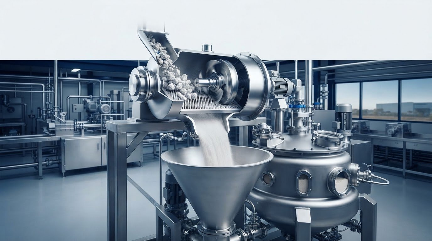
A powder blend is only as consistent as the material entering the mixer. A de-lumping mill for powders breaks down agglomerates before or during mixing, helping powder flow and blend more uniformly without necessarily reducing particle size. This matters because intact lumps can disrupt how ingredients move and distribute through the process.

Powder caking can develop during storage, transport, crystallisation, granulation or spray drying. Breaking down agglomerates can restore a more workable texture, support a consistent particle-size distribution and prepare material for the next processing step. The right approach depends on the powder’s condition and the outcome the process requires.

This article explains why de-lumping matters for mixing, how a lump breaker works and where screening may fit in bulk material handling. It also covers particle size and flow, cleanable food-processing equipment, and how to assess machinery for a production line. Use these points to decide whether de-lumping belongs before mixing, during preparation or at another stage of your process.

Key Takeaways

  • Breaking down powder agglomerates before or during mixing can support more uniform blending and steadier movement through processing equipment.
  • Rotating blades and a fixed grid or grate can reduce lumps, while opening size influences what passes through the machine.
  • Choose a de-lumping approach based on the powder’s condition and the particle size distribution the next process requires.
  • For food-grade processing, assess equipment construction and cleanability alongside how it handles the material and fits into the production line.
  • F.A. Maker’s industrial mixers and blenders can support processing lines where powder preparation and mixing need to work together.

Why is De-Lumping so Important for Mixing Processes?

De-lumping matters because powder agglomerates can interrupt how ingredients move through a mixer and distribute in the blend. Breaking them apart before or during mixing helps powder flow and blend more uniformly, without necessarily reducing particle size. This can support consistency in food, pharmaceutical and chemical processes.

In food production, stored powders can cake or form lumps, making it harder to feed ingredients steadily into a mixer. De-lumping can restore agglomerated material to its prior crumbed, flaked, powdered or clumped state. For example, a process may break up caked dry ingredients before blending them with other components. The goal is a workable feed, not automatically a finer powder.

Uniformity is especially important in pharmaceutical powder processing. Powder texture can be one consideration in tablet and capsule production. Powder flow also affects how reliably material moves between preparation and mixing. When preparing for wet granulation, the powder’s condition helps determine how to break down lumps and refine particle-size distribution.

In pharmaceutical cGMP manufacturing, equipment and process controls are considered alongside the material’s intended use. A practical sequence is to inspect the incoming powder, identify agglomerates, select a suitable de-lumping method, then assess the result for consistency. Chemical powders may also need de-lumping before mixing, since breaking agglomerates can expose more particle surface area for chemical interactions.

Several mill types can de-lump powder. A lump breaker uses rotating blades that pass through stationary comb-shaped blades, while a fixed grid or grate controls which particles pass through. Screen mills, hammer mills and pin mills are other equipment categories. The right choice depends on whether the task is to break soft agglomerates or reduce particle size further.

For Australian installations, assess machinery hazards and combustible-dust risks in relation to the material and operating conditions. Dust collection, containment, ignition-source control and suitable explosion protection are considerations in the risk assessment. Applicable Australian safety requirements depend on the installation and powder. Do not assume a general-purpose mill is suitable for combustible dust.

The cost of a powder de-lumping mill in Australia depends on the machine, its condition, capacity and process requirements. Pricing is provided after a quote request. These factors help define the equipment needed, as powders and production lines have different requirements.

Australian industrial process-equipment suppliers sell mills for powder handling, while hire availability depends on the equipment and arrangement. Compare the required feed condition, desired output and process fit when assessing supply options. A de-lumping mill for powders isn’t suitable for every material: abrasive powders can accelerate wear, heat-sensitive powders may be affected by friction, and combustible dust can create ignition and explosion hazards without appropriate controls.

How de-lumping works in bulk material handling

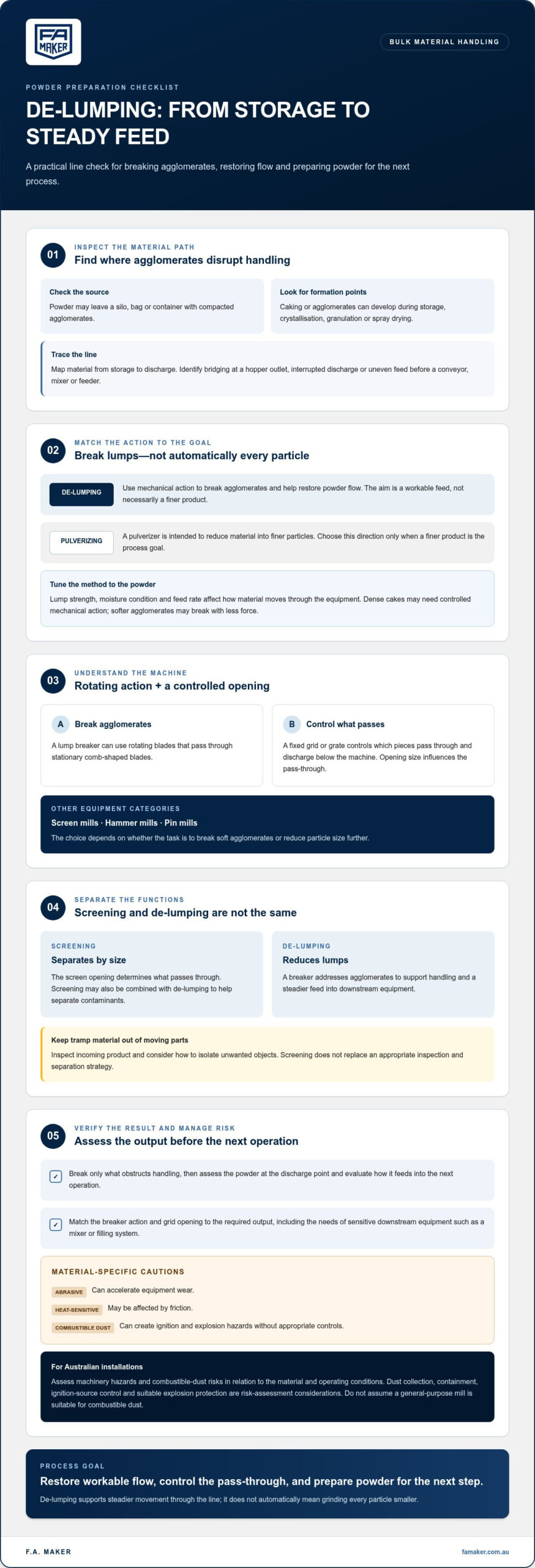
In a bulk-handling line, de-lumping is a preparation step between storage and the next process. Powder may leave a silo, bag or container with compacted agglomerates that interrupt discharge or create uneven feed. Breaking these masses helps material move into downstream equipment more steadily. The aim is to restore flow, not necessarily to grind every particle smaller.

A typical sequence starts by inspecting the incoming material and identifying where lumps form. After storage, crystallisation, granulation or spray drying, agglomerates may need breaking before a conveyor, mixer or feeder. A lump breaker can use rotating blades that pass through stationary comb-shaped blades. A fixed grid or grate then controls which pieces pass through and discharge below the machine.

“De-lumping mill” and “lump breaker” often describe overlapping equipment used to break agglomerates, while a pulverizer is designed to reduce material into finer particles. The distinction is the process goal: restoring flow by breaking lumps, or intentionally producing a finer product. Choose according to the powder’s condition and the particle size required downstream.

Compacted material needs controlled mechanical action. A dense cake can bridge at a hopper outlet, while softer agglomerates may break with less force. Feed rate, moisture condition and lump strength affect how material moves through the equipment. Assess the powder at the discharge point, break only what obstructs handling, then evaluate how it feeds into the next operation.

Screening can be combined with de-lumping to help separate contaminants from material. The screen opening determines what passes through, while de-lumping addresses agglomerates. These functions are related but distinct: a screen separates by size, while a breaker reduces lumps. Account for both in the process line, especially before sensitive downstream equipment such as a mixer or filling system.

Address tramp material before it reaches moving parts. Inspect incoming product and consider how to isolate unwanted objects before they enter the breaker. Screening may help remove contaminants, but it does not replace an appropriate inspection and separation strategy. The arrangement depends on the contaminant, powder properties and equipment layout.

For a reliable handling sequence, map the material path from storage to discharge, then identify where bridging or inconsistent feed occurs. Match the breaker’s action and grid opening to the required output, and place screening where separation is useful. If the line continues into packaging, review downstream process equipment as part of the overall material-handling layout.

Particle size distribution and powder flow

De-lumping supports powder flow by breaking agglomerates while preserving particle characteristics needed downstream. The goal is a suitable size distribution, not maximum size reduction.

Powder Integrity and Flow

Powder integrity means retaining useful particle characteristics rather than grinding material unnecessarily. Excessive size reduction can change how a blend handles and create fines that move differently from larger particles. Assess how the powder discharges, feeds and mixes after treatment. A material that bridges only because of soft agglomerates, for example, may need gentle breaking rather than further grinding.

Improved flow depends on how particles interact, not simply on achieving the smallest particle size. A broad size distribution can affect how powder packs and moves through equipment. Compare samples before and after processing, focusing on visible lumps, discharge consistency and feed behaviour. These observations help determine whether de-lumping has restored usability while maintaining the material’s required integrity.

Powder Properties and Throughput

Choose equipment by matching its breaking action to the powder’s condition and required throughput. Consider whether the feed is cohesive, compacted, fragile or free-flowing, then assess how consistently it enters the mill. De-lumping should address agglomerates without imposing unnecessary particle-size reduction. The required throughput also depends on feed rate and how the material behaves during discharge.

Review the process as a connected line. A steady mill output is useful only if the next feeder, mixer or conveyor can accept it. Note where feed surges or interruptions occur, then compare operating conditions before and after treatment. This makes throughput a practical line requirement rather than an isolated machine figure.

Particle Sizes and Capacities

Output particle size depends on the mill’s breaking mechanism and the opening size of its grid, grate or screen. In a lump breaker, material small enough to pass through the openings discharges, while larger agglomerates remain for further breaking. Capacity depends on feed behaviour, equipment configuration and required output. Together, these factors determine the usable operating range.

Internal particle-size classification occurs when a screen or grate retains oversize material while allowing smaller particles through. This can support a more controlled output, but it does not make every particle identical in size. Define the acceptable size distribution for the next process, then assess discharged material against that requirement. With a de-lumping mill for powders, evaluate particle size and throughput together, since changing the opening or feed rate can affect both flow and output consistency.

Nor does screening remove the need to assess powder after processing. In pharmaceutical manufacturing, refining particle-size distribution and removing lumps can improve powder flow through processing equipment. For wet granulation preparation, breaking down powder lumps can help achieve a more uniform particle-size distribution; the method depends on the powder’s condition. Match the de-lumping action to the material while keeping the desired distribution in view. The goal is more uniform material that flows better through processing equipment, not size reduction for its own sake.

De-lumping Mill for Powders for Better Mixing and Flow

Food-grade construction and cleanability

For food processing, cleanability starts with the machine’s product-contact surfaces and internal access. Powder residues can collect around screens, blade assemblies, seals and discharge points. When selecting equipment, map these areas against your facility’s cleaning method. A design that allows practical inspection and access can make routine cleaning more manageable.

Assess food-grade construction against the product, cleaning regime and production environment. Confirm that product-contact materials suit the powder and cleaning agents, and review the finish of surfaces, joints and seals. For example, sticky confectionery powder may leave deposits in corners where a free-flowing ingredient would not. The machine’s construction must suit the actual material and changeover needs.

Install the machine in line with the process layout, allowing access to the feed, discharge and components that need inspection. Connect upstream and downstream equipment so powder transfers without unnecessary ledges or residue traps. Follow the equipment instructions and site procedures for cleaning and maintenance, including isolation before access and inspection for retained product after cleaning.

  • Before installation: identify the powder, expected flowability and cleaning method, then check machine access and connections.
  • Before cleaning: stop the process and follow site isolation procedures before opening covers or accessing internal components.
  • During cleaning: remove retained powder from screens, blades, seals and discharge areas using the facility’s approved method.
  • After cleaning: inspect accessible product-contact areas and reassemble components according to equipment instructions.

These steps matter during product changeovers. Residue from one food powder can carry into the next batch if inspection misses a screen edge or discharge housing. A documented sequence helps operators clean the same areas consistently. Tailor it to the machine’s construction, the powder’s tendency to adhere and the cleaning method used on site.

Maintenance also affects cleanability and flow. Worn seals, damaged screens or poorly seated components can create places where powder collects. Include these parts in planned inspections, and check for buildup when flowability changes or discharge becomes uneven. Service or replace components according to equipment guidance and site maintenance procedures.

For Australian food production, treat cleanability as a process-design criterion, not merely a surface feature. Review how the machine fits the facility’s hygiene procedures, changeover sequence and powder characteristics. A suitable arrangement makes inspection practical while supporting reliable material flow through the production line.

Powder agglomeration and deagglomeration

Powder agglomerates form when particles adhere during storage, transport or exposure to environmental conditions. Moisture, pressure and handling can change how a material behaves, leaving powder that no longer feeds as it did originally. De-lumping restores the material towards its prior crumbed, flaked, powdered or clumped condition. The objective is to address unwanted clumping, not automatically to produce finer particles.

Choose the method according to whether the material is dry or dispersed in liquid. Dry milling breaks agglomerates through mechanical action without adding liquid. Wet milling uses mechanical agitation while powder is dispersed in liquid media. Ultrasonic mixing uses cavitation generated by ultrasonic waves to disrupt agglomerated material. Each method works differently, so match the process to the material’s condition and the next operation.

For example, dry powder that cakes after transport may need mechanical de-agglomeration before feeding or blending. Powder already suspended in liquid may call for a wet process instead. The distinction matters: adding liquid to a dry-handling line changes the process, while dry milling does not address a suspension in its current state. Identify the powder’s physical state first.

De-agglomeration can also support chemical processing. Breaking clumps exposes more particle surface area for chemical interactions, which can improve mixing efficiency and increase reaction rates. This is relevant when pretreating catalysts and other reactive substances. The useful endpoint is material prepared for its intended interaction, not maximum milling energy or the finest achievable output.

In suspensions, larger agglomerated particles can settle towards the bottom. Breaking them apart can help limit settling and improve mixture stability. Dispersants, including surfactants, can help prevent particles from agglomerating by reducing surface tension. They complement mechanical processing rather than doing the same job, so consider whether the issue is existing clumps or particles forming new ones.

A practical selection sequence is to:

  • Identify whether the powder is dry, suspended or already mixed.
  • Determine whether agglomerates formed during storage, transport or processing.
  • Set the required condition for the next step, such as feeding, mixing or reaction.
  • Compare mechanical milling, wet agitation, ultrasonic mixing or dispersants against that need.

These checks help distinguish deagglomeration from size-reduction milling and guide a process that uses only the action required. To consider equipment for powder handling, explore powder-processing equipment suited to your production line.

De-lumping is useful when material changes form during storage, transport or exposure to environmental conditions. It can restore agglomerated material to its prior crumbed, flaked, powdered or clumped state. The appropriate target is that prior condition, not an assumption that every powder must become finer. For dry material, dry milling breaks down agglomerations through mechanical action without using liquids, distinguishing it from processing a suspension.

In a suspension, de-lumping can help prevent larger particles from settling to the bottom and improve mixture stability. During pretreatment, de-lumping catalysts and other reactive substances can expose more particle surface area and support chemical mixing efficiency. These applications have different goals: maintaining mixture stability or preparing reactive material for chemical mixing. Select the process according to the material’s state and the task.

F.A. Maker: Used Stainless Steel Tanks

F.A. Maker supplies used stainless steel tanks and industrial mixers and blenders for processing lines where powder preparation connects with storage or mixing. Once you’ve identified where de-lumping fits, consider the surrounding equipment: a suitable mixer receives prepared powder, while tanks can support storage or other process stages. F.A. Maker also supplies pumps and valves, and centrifuges and separators for broader process-equipment needs.

Turn to F.A. Maker when assessing equipment for a production line that handles powders alongside storage, mixing or transfer operations. Considering these offerings together helps you assess the line as a connected process rather than treating each machine in isolation.

For information about F.A. Maker’s process equipment, visit famaker.com.au.

Set the Next Process Step

Before selecting a de-lumping mill for powders, define the material condition the next stage needs to receive. Record how the powder behaves at the feed point, what output condition supports your process, and how operators will assess the result. These criteria provide a practical starting point for equipment discussions and keep the decision tied to production requirements.

Consider the wider line as well. Powder preparation may need to work alongside mixing, storage or separation equipment, so pay attention to the interfaces between stages. F.A. Maker offers Industrial Mixers and Blenders, Used Stainless Steel Tanks, and Centrifuges and Separators for processing operations. These categories can help you consider equipment needs across connected stages without losing sight of the specific powder-handling task.

Use your process requirements to guide the next conversation. Contact F.A. Maker about powder-processing equipment and take the next step towards a setup that fits your operation.

Frequently Asked Questions

What is a de-lumping mill for powders and how does it work?

A de-lumping mill for powders breaks soft or compacted powder agglomerates so material can feed more consistently into the next process. For example, a production line may place one between a storage hopper and a mixer when caked feed disrupts dosing. Assess the incoming material and desired output, then select a suitable machine arrangement. De-lumping does not automatically mean grinding the powder finer.

How much does a powder de-lumping mill cost in Australia?

Cost depends on the machine, its condition, capacity and process requirements. Pricing is provided after a quote request.

Industrial Solids Separation Equipment for Liquid Slurries

A separator is one part of liquid-solid separation, a process that removes solid particles from a liquid slurry through filtration, gravity settling or centrifugation. Industrial solids separation equipment uses these methods to separate the phases, recover solids or liquid, or prepare material for further processing. The right method depends on the slurry and what the process needs to recover.

Filtration passes the mixture through a medium that retains solids while liquid flows through. Sedimentation lets particles settle before the clearer liquid is decanted, while centrifugation spins the mixture to move solids outward from the liquid. In practice, pretreatment and solids concentration can reduce the amount of slurry entering the separation stage.

This guide explains how the methods work, how continuous and batch equipment handle slurries, and where separation is used in industries such as mining, food, chemicals, coatings, ceramics and water treatment. It also covers the process factors that shape equipment selection, helping you understand how a separation system fits into a wider production line.

Key Takeaways

  • Liquid-solid separation removes particles by filtration, gravity settling or centrifugation; the method depends on the slurry and what the process needs to recover.
  • Compare filtration and sedimentation by how each handles solids: filters retain particles, while settling allows them to collect before liquid is decanted.
  • Separation supports different goals across industrial processes, including recovering solids, reclaiming liquid and clarifying water.
  • For continuous operation, consider equipment such as belt filter presses and rotary drum filters, which remove water as slurry moves through the process.
  • Match equipment to particle size, slurry consistency, processing volume, continuity, industry requirements and maintenance needs.

What is liquid-solid separation?

Liquid-solid separation removes suspended or mixed solids from a liquid slurry. It can recover the solid, clarify the liquid, or prepare both streams for reuse or further treatment. For example, a mineral-processing plant may separate tailings solids from water to support water recovery and reduce environmental impact.

Centrifugation separates phases by spinning the slurry. Centrifugal force moves denser solids towards the bowl wall, while the liquid stays nearer the centre. The separated streams can then be discharged continuously or collected for the next process step. This method is useful when gravity settling alone cannot deliver the required separation rate.

In an industrial centrifuge, the rotating bowl creates the separation force. A decanter centrifuge has a scroll conveyor inside the bowl that moves settled solids towards a discharge point while clarified liquid exits separately. Feed rate, bowl speed, slurry consistency and particle characteristics all affect performance. A change in feed composition can shift the balance between liquid clarity and solids dryness.

Decanter centrifuges can support tailings treatment by separating water from mineral solids. Recovering liquid can reduce the need for additional process water, while discharged solids move to handling or storage. Equipment must suit the slurry’s particle size, abrasiveness and throughput, as these properties affect wear and separation results.

Operating costs include electricity for the drive, water for cleaning, and consumables such as lubricants and wear parts. Energy use depends on motor load and operating hours; water and consumable use vary with cleaning frequency, slurry characteristics and equipment design.

For Australian procurement, F.A. Maker offers centrifuges and separators, including decanters. Other suppliers and manufacturers also serve industrial process requirements, with equipment selected against the material, process duty and required output.

Installation requires a suitable foundation, correctly aligned connections, and integration with feed, discharge and control systems. During operation, monitor feed conditions, vibration, separation quality and discharge. Maintenance includes inspecting and cleaning wetted areas, checking wear components, and servicing rotating assemblies according to equipment requirements.

Common failure modes include imbalance from uneven solids build-up, blocked outlets, worn scrolls and leaking seals. Hazards include contact with rotating components, unexpected movement during maintenance, noise, hot surfaces and exposure to process chemicals. Guards, safe isolation before inspection, and controlled cleaning help manage these risks.

At its simplest, centrifugation separates the two phases by their position during rotation: solids move outward to the slurry’s edge, while liquid stays near the centre. The spinning action places the solid and liquid portions in different locations without changing what either portion is.

Once the phases occupy separate positions, the process can recover the solid fraction, the liquid fraction, or both, depending on the objective. The defining action is the same: spinning moves solids to the edge and leaves liquid near the centre. This is the basic principle behind centrifugation of a liquid-solid mixture.

Filtration and sedimentation processes

Filtration and sedimentation separate solids from liquid in different ways. A filter medium retains particles as slurry passes through, while liquid flows onward as filtrate. Sedimentation uses gravity to settle particles in a vessel before clearer liquid is decanted. The choice depends on particle size, settling behaviour, slurry concentration and the required quality of each output stream.

In filtration, solids collect on the filter medium and form a cake. As the cake thickens, it can capture finer particles, but it also resists liquid flow. Operators balance feed rate, pressure and cake removal to maintain the required throughput. Vacuum filtration draws liquid through the cake using a pressure difference somewhat less than 1 atmosphere (14.7 psi).

A filter press handles slurry in batches. Its plates hold filter cloths that trap solids while filtrate passes through drainage channels. Once the chambers fill, the cycle stops so the cake can be discharged before another batch begins. Filter presses suit batch duties where solid recovery or a drier cake matters. In mineral processing, filtration can produce filter cake containing 80%-90% solids.

Cloth selection affects filtration rate, particle retention and cake release. Cloth with too open a weave can let solids into the filtrate; finer cloth may restrict flow or blind as particles accumulate. Material compatibility also matters, particularly in chemical service. Regularly inspect for tears, blinding and poor sealing to maintain separation and filtrate recovery.

Sedimentation equipment allows particles to settle before liquid leaves the vessel. Clarifiers and thickeners use gravity to handle large volumes, with thickening producing a denser underflow and comparatively clear overflow. In sizing gravity equipment, settling velocities above 0.4-0.5 m/h warrant experimental verification and further study. Particle size, density and slurry behaviour shape the settling rate.

For continuous water treatment, a clarifier can separate settleable solids before downstream filtration. For batch production, a press can collect solids and recover filtrate in distinct operating cycles. A belt filter press removes water by squeezing and shearing slurry between two endless filter belts; it can operate at pressures up to 0.8 bar. The process choice should reflect whether the plant prioritises continuous flow, cake handling or liquid clarity.

F.A. Maker offers filter presses for industrial filtration duties. If a press suits the process, review the available filter press equipment as part of planning filtration and filtrate recovery.

If a gold-processing slurry requires solid-liquid separation, a countercurrent decantation circuit or a filter can recover solution containing most of the cyanide and copper cyanide species. These are two separation options for that slurry, with solution recovery identified as their purpose. The example links the choice of process to recovering solution while separating the solid and liquid portions.

More broadly, the paper describes mechanical separation equipment as relying on sedimentation or filtration, with the possible exception of impingement equipment. This description places the main equipment approaches in one of those two process categories while retaining impingement equipment as a possible exception. Sedimentation and filtration therefore provide the framework for describing mechanical separation, while the gold-processing example identifies a recovery application within that framework.

Industrial Solids Separation Equipment for Liquid Slurries

Applications in food, chemicals, coatings, ceramics and water treatment

Separation duties vary across Australian industries because slurries differ in their solids, liquids and product requirements. Food processing may remove suspended material from a product stream, while a chemical plant may recover solids or clarify process liquid. Equipment choice depends on the required output quality, material compatibility and whether the process runs continuously or in batches.

In food and beverage production, separation can clarify liquid ingredients or remove solids before a later processing step. Dairy and brewery streams, for example, may contain suspended material that affects product consistency or downstream treatment. Centrifugal force separates phases by density, while filtration retains particles on a medium. Product-contact materials and cleaning procedures matter because residues can affect subsequent batches.

Chemical slurries require attention to both liquid and solid properties. Corrosive or reactive mixtures may require specialised membrane- or centrifuge-based systems selected for compatibility with the process. Coatings and ceramics can produce fine-particle slurries; filtration or sedimentation can separate solids for recovery, liquid reuse or controlled handling. Particle size and settling behaviour help determine which mechanical process is suitable.

Mining uses solid-liquid separation to recover solids, liquid, both streams, or to clean liquid before discharge. Tailings thickening uses a large-area circular tank: solids settle into a denser underflow, while a comparatively clear overflow can return to the process. Recovering this water can reduce demand for additional supply and help minimise the environmental impact of tailings management. Clarifiers and thickeners use gravity to settle solids while handling large volumes.

Water treatment applications include removing suspended particles before further treatment or reuse. The separation stage may combine gravity settling with filtration, depending on the incoming water and required downstream process. Some filtered waters have a turbidity target below 0.1 NTU at the 95th percentile and a maximum of 0.3 NTU. These values illustrate how a defined water-quality objective can shape process design.

Australian work health and safety and environmental requirements operate through applicable Commonwealth, state or territory frameworks, with obligations shaped by the site and process. Operators need to account for machinery hazards, chemical exposure, waste handling and discharge conditions when designing and operating a system.

For mining tailings, assess slurry characteristics, decide whether water or solids recovery is the priority, then select and integrate suitable equipment. Centrifugal force can support separation where density differences matter; gravity sedimentation suits settling solids and large-volume duties. In every application, performance depends on matching the process to the material and intended output.

Continuous removal of solids from liquid slurries

Continuous systems separate a moving slurry without stopping production for each batch. Their design depends on the separation objective, feed behaviour and the next process stage.

Separation Methods and Purposes

Mechanical separation and sedimentation are two common approaches. Filtration retains particles on a medium, while gravity settling lets them collect before liquid moves onward. Flotation uses tiny air bubbles that attach to particles and carry them to the surface for removal. Choose a method according to whether the process prioritises solids recovery, liquid clarification or both, and whether the slurry must flow continuously.

Equipment Selection Criteria

Choose equipment by assessing particle size, slurry consistency, required throughput and whether the process runs continuously or in batches. Fine particles may need different treatment from coarse, granular solids; thick sludge also behaves differently from dilute feed. First define the target output, then assess feed variability, industry requirements, budget and maintenance demands. Together, these factors determine which method suits the process.

In mineral processing, separation can recover solids, process liquid, both streams, or clean liquid before discharge. A hydrocyclone can make fine particle-size cuts as a pretreatment or solids-conditioning step before another separator. It spins liquid inside a stationary chamber, unlike a centrifuge, whose chamber rotates. Hydrocyclones are most effective with granular particles whose specific gravity is about three times that of the liquid.

For liquid screening, a vibratory sieve moves slurry across a screen surface. Liquid and particles smaller than the openings pass through, while larger solids remain for removal. Screen aperture, feed rate and the slurry’s tendency to blind the mesh affect performance. Vibratory screening can therefore serve as an initial separation step when oversized particles need to be removed before downstream treatment.

A rotary drum filter can process slurry continuously as its rotating surface forms a filter cake. A reversed air blast and scraper knife remove the partially dried cake as the drum turns. This arrangement suits large slurry volumes where regular cake discharge is part of the process. The filtrate and removed solids can then be directed to separate recovery or handling stages.

For reliable continuous operation, consider feed distribution, solids discharge and cleaning access. Buildup on a screen or rotating surface can restrict flow and disrupt separation. Maintenance planning should account for wear on contact surfaces, screen condition, scraper performance and the route for discharged solids. In a mineral plant, aligning these checks with feed conditions and downstream processing helps maintain consistent separation.

Industrial separation equipment

Australian plants use centrifuges, decanters, filter presses, rotary vacuum filters, screens, hydrocyclones, clarifiers, thickeners, flotation systems and membranes. Each method suits a different feed or separation duty, so equipment selection should start with the material and required output.

A practical process train often combines equipment rather than relying on one separator. A screen can remove coarse material before a hydrocyclone makes a fine particle-size cut. The hydrocyclone conditions solids for a later separation step; it spins liquid inside a stationary chamber, unlike a centrifuge, whose chamber rotates. Granular particles with a specific gravity about three times that of the liquid suit hydrocyclone separation.

For large-volume liquid duties, clarifiers and thickeners use gravity to settle solids. A thickener produces a denser underflow and a comparatively clear overflow. In continuous countercurrent decantation, a series of thickeners moves underflow upstream, so concentrated solids and clarified liquid travel in opposite directions. This arrangement can support solution recovery in mineral processing.

Filtration equipment suits different operating patterns. Filter presses handle batch jobs, while rotary vacuum filters process large slurry volumes. Disc filters handle demanding mineral-processing duties, including dewatering lead-zinc-copper concentrate, low-grade iron ore-taconite, coal and aluminum hydrate. Choose according to the feed, cake-handling requirements and whether the operation needs batch or continuous processing.

Flotation separates particles by attaching air bubbles to solids and carrying them to the surface for removal. Rotor-stator devices whip air into the fluid; dissolved-air flotation releases pressurised air into a tank, where escaping bubbles attach to particles. Membrane separation uses pressure to move liquid through a membrane while retaining tiny solid particles. Each method suits different materials and process objectives.

Select equipment according to the separation objective: recover solids, recover liquid, recover both, or clean liquid before discharge. Then assess particle size, slurry consistency, throughput, process continuity, industry requirements, budget and maintenance demands. Chemical-processing slurries involving corrosive or reactive materials may require specialised membrane- or centrifuge-based systems.

For mineral circuits, consider lower-cost, high-throughput pretreatment before expensive separation operations. A hydrocyclone can condition feed; a thickener can concentrate solids; filtration can then produce a manageable cake. Matching each stage to the material helps prevent downstream separators from handling unnecessary slurry volume.

To assess processing equipment options for your operation, discuss your equipment requirements.

F.A. Maker: Used Stainless Steel Tanks

F.A. Maker supplies used stainless steel tanks and process equipment for Australian production operations. Its range includes centrifuges and separators, industrial mixers and blenders, and pumps and valves to support separation processes and related production stages.

These products support different stages of a process line: centrifuges and separators handle separation duties, pumps and valves move and control process streams, and mixers and blenders prepare materials before processing. Consider F.A. Maker when sourcing equipment for a production setup or reviewing machinery for an existing line.

For equipment enquiries, contact F.A. Maker or visit famaker.com.au.

Plan the next step for your process

Turn the separation requirement into a practical equipment brief before narrowing your options. Record how the slurry changes during production, where each output stream goes, and how the separator must connect with upstream and downstream machinery. Include available floor space, utility connections, cleaning access and the operating pattern. This gives your team a clear basis for assessing industrial solids separation equipment against the full process, rather than an isolated task.

F.A. Maker offers Used Stainless Steel Tanks, Centrifuges and Separators, and Industrial Mixers and Blenders. These categories can be useful when reviewing equipment for separation, material preparation and process-line integration. A concise brief describing your application and intended outputs can focus the discussion on equipment suited to your operation.

Use your process requirements as the starting point, then contact F.A. Maker about your process to discuss the next step. A structured equipment review can help you move forward with a clearer view of the production line.

Frequently Asked Questions

How do screens, centrifuges, filters and clarifiers compare for industrial solids separation?

Each method handles different feed conditions and separation targets. Screens retain particles larger than their openings, making them useful for coarse material. Centrifuges separate phases by density and suit slurries where settling needs to be accelerated. Filters capture solids on a medium, while clarifiers let particles settle in a tank. For example, a plant might screen incoming slurry first, then use a centrifuge or filter to meet its required output quality.

What are typical capacities and separation efficiencies for industrial solids separation equipment?

Capacity and separation efficiency depend on equipment design and the material being processed, so there is no single representative figure. Feed flow, particle size, solids concentration, viscosity and the required clarity or dryness all affect performance. A dilute slurry with fine particles, for instance, presents a different duty from a thick feed containing coarse solids. Compare equipment using the same feed conditions and target outputs, including expected variation during normal operations.

How to Choose a Ribbon Blender for Your Production Needs

The right ribbon blender is sized around the batch you actually run, not simply the largest capacity available. The main criteria for selecting a ribbon blender are batch size and production rate, with working volume generally set at 40%–70% of the vessel’s total volume. Mixing time, product characteristics, construction materials, surface finish and wear protection also affect whether the machine suits your process.

Capacity is a sensible place to start, but it is only one of the criteria for selecting a ribbon blender. The blender must handle your ingredients consistently, meet the production schedule, and suit your operation’s cleaning and wear requirements.

Assess output and full-cycle time, choose materials and finishes to suit the product, and account for abrasion. Comparing these practical specifications helps narrow the options to a blender suited to your batches and production needs.

Key Takeaways

  • Size the blender using your regular batch weight, material bulk density and production schedule, rather than vessel capacity alone.
  • Assess mixing time alongside motor demand; design choices that speed blending can also increase power requirements.
  • Match construction material and abrasion protection to the product’s corrosiveness, cleaning needs and wear characteristics.
  • Specify interior finish, weld design and access around the cleaning standard your process requires.
  • Compare the mixer’s dimensions, working volume and discharge arrangement with both your batch and downstream handling needs.

1. Production rate, mixing time and number of mixers

Start with the production schedule. Record the required batch weight, batches per shift, and finished output per hour or day. Then account for loading, ingredient addition, mixing, discharge, and cleaning between formulas. Mixing time alone does not describe the full cycle: a blender that mixes quickly may still limit output if loading or discharge takes longer.

For ribbon blender mixing time and blend uniformity, standard materials may reach a homogeneous blend in 3–15 minutes; ribbon feed mixers typically blend a batch in 3–10 minutes. A single-shaft batch blender typically takes about 2 minutes to mix most materials, but actual results depend on ingredients and process conditions. For compound feeds, a coefficient of variation (CV) of ≤10% is generally acceptable; premix production should target ≤5%.

Use batch weight and bulk density to compare capacity ranges. A 100–300 L mixer is listed for typical batches of 50–200 kg, while a 500–1,500 L unit is listed for 300–1,000 kg. Larger production may suit a 2,000–5,000 L mixer, listed for 1,200–3,500 kg batches. These ranges are starting points, not substitutes for matching the actual powder and formula to a working volume.

Estimate batch frequency using the complete cycle. Divide planned production volume by usable batch weight, then compare the required batch count with available operating hours and changeover time. If one mixer cannot meet the schedule, consider a second mixer, staggered batch preparation, or a process change. Two agitator sets can shorten mixing time, but require more horsepower.

Check the proposed equipment against the facility layout before settling on capacity. Map the mixer footprint alongside ingredient feed, operator access, discharge clearance, and the next conveyor or packaging stage. Test future batch weights against the same layout and line sequence to allow for planned production growth. A mixer that fits today’s formula may restrict a larger batch or an additional ingredient stream later.

Check integration at both ends of the vessel. Confirm that upstream feeders deliver ingredients without interrupting batch timing and that the discharge outlet aligns with the receiving conveyor, hopper, or container. A fast discharge can still create a bottleneck if downstream equipment cannot accept material at the same rate.

Set measurable acceptance criteria before purchase. Define the batch-size range, maximum cycle time, blend uniformity, liquid-addition needs, allowable residual quantity, and cleaning standard. For difficult chemical formulas or high-consequence products, testing representative product is more reliable than relying on assumptions based on a similar application.

Validate uniformity by collecting 10 samples of 100–200 g from different mixer locations and depths, or from the discharge stream. Test at commissioning and annually, or after a significant formulation or process change. Compare results with the target CV, then assess whether mixing time, batch loading, or ingredient sequence needs adjustment.

2. Construction materials, finishes and abrasion-resistant linings

For food or chemical applications, stainless steel grades 304 or 316 are common construction choices. Pharmaceutical contact surfaces may use 316L stainless steel with a finish of Ra ≤ 0.4 μm. Hazardous volatile powders may require explosion venting arranged to direct blasts away from workers. These options address different process risks, so match the material and features to the ingredients and operating conditions.

Stainless steel resists corrosion and is straightforward to clean, making it a practical option for corrosive products, food processing, or frequent washdowns. Carbon steel costs less but can corrode, potentially affecting product-contact surfaces. For abrasive minerals or similar ingredients, a polyurethane coating or replaceable steel liner can protect areas exposed to repeated wear.

Surface finish affects how ingredients behave against the vessel wall. Sticky, high-fat or hygroscopic food materials can adhere to rough surfaces, so a polished finish of Ra ≤ 0.8 μm is recommended for these applications. A finer finish may be appropriate for stricter purity needs. Specify the required finish for product-contact surfaces rather than describing the vessel simply as polished.

Sanitation depends on more than the base metal. Rounded internal corners and crevice-free welds can reduce places where material collects and bacteria may build up. A polished interior can support cleaning validation in pharmaceutical blending and help limit cross-contamination between formulas. Specify cleaning methods alongside finish requirements, particularly when operators change between products.

Seals contact both ingredients and cleaning agents. Check whether the seal material is compatible with the powder, any liquid addition, wash chemicals, and process temperatures. A seal that degrades or leaks can let product enter the shaft area or create a path for contamination. Include seal access and replacement in the maintenance plan.

Ribbon, paddle, ploughshare, and V-blenders use different mixing actions. A ribbon blender moves powders in opposing directions with inner and outer helical ribbons; paddle and ploughshare designs use their respective mixing tools. A V-blender tumbles material as its vessel rotates. The right action depends on product flow, fragility, required turnover, and whether the process needs more than blending.

For an efficient specification, list each ingredient’s corrosiveness, abrasiveness, moisture, cleaning needs and purity requirements. Then match those conditions to vessel material, finish, lining and seals. If you’re comparing machinery with process vessels, stainless steel process equipment can be part of the wider production-line review.

3. How to Choose the Right Ribbon Mixer?

Calculate vessel capacity using the largest batch weight, bulk density at plant conditions, and target fill fraction. Working volume equals batch weight divided by bulk density; total vessel volume equals working volume divided by the target fill fraction. This calculation translates production requirements into a practical machine size.

For example, a 300 L batch may call for a mixer with approximately 500–600 L total volume. A 2 cubic metre batch may require approximately 3.3–5 cubic metres of total vessel volume. These examples show why batch size and total volume are not interchangeable: the vessel needs space for the ribbons to move material through the mix.

Ribbon blenders generally work within a product-dependent fill range. A useful starting range for working volume is 40%–70% of total vessel volume. Filling below 30–40% can reduce consistent contact with the upper outer ribbon; filling above 70–80% can restrict the space needed for shearing and convective movement. Use actual bulk density and the product’s flow behaviour to refine the target.

Choosing capacity also means checking the smallest regular batch, not only the maximum. If production varies, compare both extremes with the mixer’s rated volumetric capacity. A batch should contain at least 30–40% of rated capacity for optimal mixing. If low-volume runs fall below that range, a smaller machine or a separate production plan may prevent inconsistent ribbon contact.

Assess throughput by comparing working batch weight with the required production schedule. Divide the required output by batch weight, then account for loading, mixing, discharge, and changeovers. A mixer sized for the largest batch may still fall short of the required daily output if each formula needs extended cleaning or frequent ingredient changes.

Dimensions matter alongside volume. A batch ribbon blender typically has a length-to-width ratio of 2:1, but the overall footprint must also accommodate loading access, drive components and discharge equipment. Measure the available plant space, including the route for moving the machine into position. For pharmaceutical production, include access for inspection and cleaning in the layout review.

Allow for process changes without oversizing every batch. A blender with capacity about 20% greater than the largest batch can provide flexibility as demand changes. However, keep routine batches within the suitable fill range. Compare expected future batch weights against both the minimum and maximum working volumes before finalising specifications.

Record bulk density, batch weight, and target fill level for each formula. Use the highest and lowest values to test the proposed capacity, then assess the footprint and discharge arrangement. This makes mixer selection a measurable fit between product volume, production needs, and available facility space.

How to Choose a Ribbon Blender for Your Production Needs

4. Surface finish and weld design to reduce buildup

Choose the internal finish to match the product and cleaning method. A standard industrial-grade finish is listed as Ra ≤ 0.8 μm. For pharmaceutical or high-purity ribbon blender surfaces, a finer Ra ≤ 0.2 μm finish with electropolishing is specified. For food materials that are sticky, high-fat or hygroscopic, a polished finish of Ra ≤ 0.8 μm can reduce surface adhesion.

Weld geometry matters as much as the measured finish. Rounded internal corners and crevice-free welds help limit places where product can accumulate or bacteria can build up. In pharmaceutical blending, a polished interior can support cleaning validation and reduce cross-contamination risk. Include the vessel, shaft, ribbon, discharge area, and product-contact joints in the finish specifications.

For Australian installations, assess hazards and workplace controls as part of equipment selection. Consider guarding, safe access, lockable electrical disconnects for maintenance, and explosion venting for volatile powders. These features address different risks, so specify them according to the material handled and the operating environment. A smooth finish alone is not a complete safety measure.

Motor and speed selection must suit the product load. The drive needs enough power to move the ribbons at the target speed under full load, including startup under load. Ribbon feed mixer shaft speeds typically range from 30 to 100 RPM, adjusted for ingredient bulk density and fragility. Higher speeds can improve mixing efficiency but may increase wear, while excessive speed can incorporate unwanted air.

Temperature-sensitive ingredients may need a jacket around the vessel, which can circulate steam or cool water to heat or cool the contents. Match the discharge valve to sanitation needs, product flow, sealing, and the transfer equipment below. A drop-bottom gate opens across the bottom for rapid discharge; a single gate suits longer batch cycles without a rapid discharge requirement.

Loading and cleaning arrangements affect day-to-day operation. Fully openable lids can help with manual cleaning and inspection, while dust-proof sealed covers suit fine powders. Clean-in-place spray balls can support automated cleaning without disassembly, and full-diameter access doors improve visual inspection. For wet cleaning, consider drainage and whether cleaning coverage suits the product and soil type.

Ribbon geometry also influences movement and wear. The inner and outer ribbons move ingredients in opposite directions, creating convective mixing. A typical recommended gap between the blade edge and inner trough wall is 3–6 mm. Include this clearance in specifications, then consider how abrasion, buildup or blade damage could alter it during operation.

Plan maintenance around inspection, lubrication, drive alignment, and component replacement. When plant maintenance teams handle in-house repairs, shaft modifications, or machining upkeep, technical guides from ridiculousmachinetools.com can assist with workshop tooling setups. Wear can change clearances and leave residues, while retained product can contaminate the next formula. Specify access for inspecting welds, seals, blades, and discharge surfaces so maintenance teams can identify buildup or damage before product quality is affected.

5. Ribbon mixer selection criteria

Match the mixer to the product’s behaviour, not just its name. Ingredients with different particle sizes, shapes, moisture levels, or densities can mix unevenly, even when the batch fits the vessel. Record ingredient ratios and trace-addition levels for each formula, then identify properties that could cause segregation or poor distribution.

Density differences are especially important. Ribbon blender configurations can be customised for bulk-density ratios as wide as 1:3, but that does not make every formulation suitable. A large difference in ingredient density, combined with a small quantity of an active ingredient, calls for representative product testing and a defined uniformity target.

Treat the agitator and construction as a matched system. The inner and outer ribbons move material in opposite directions, creating convective movement through the trough. A double-ribbon arrangement adds a ribbon and shaft, which can improve turnover for dense or difficult-to-blend products. The drive must still suit the material’s resistance and operating conditions.

Liquid addition changes the mixing task. Assess the liquid-to-solid ratio, viscosity, temperature, pump, nozzle, addition duration and cleaning method. For minor liquid ingredients, atomising nozzles on a spray bar can distribute the addition across dry material. Introduce liquid after the dry ingredients have partially blended, at approximately 60–70% of total mix time, to help limit local wet spots.

Recognise when a ribbon blender is not suited to the application. Very cohesive powders, sticky materials, high-liquid formulations, and products requiring intensive deagglomeration may need another mixing approach. Ribbon blenders may also be unsuitable for rapid vacuum drying, reaction control, intensive emulsification, or continuous processing. Matching the equipment’s action to the process objective helps avoid a poor fit.

Specify discharge and retention separately. For high-value formulations, material left inside can affect yield, allergen control, active-ingredient accountability, and the next batch’s quality. Define the allowable residual quantity, product flow needs, sealing, and receiving equipment. Paste-like or slurry applications need liquid-tight discharge valves, since some blender valves are only dust-tight.

Turn the criteria for selecting a ribbon blender into measurable acceptance requirements: formula range, density variation, liquid addition, blend uniformity, maximum cycle time, residual quantity, and cleaning standard. Test representative product when formulation behaviour is difficult to predict or failure has serious consequences. This turns a general equipment description into a process-specific purchase specification.

Use these requirements to compare ribbon blender options against your applications and production process.

F.A. Maker: Used Stainless Steel Tanks

F.A. Maker supplies industrial mixers and blenders, including ribbon blenders, alongside used stainless steel tanks. Once you have defined batch range, material compatibility, cleaning needs, and discharge requirements, these specifications provide a practical basis for identifying equipment suited to your process. F.A. Maker also supplies pumps and valves, as well as centrifuges and separators, for production lines that need supporting equipment.

Turn to F.A. Maker when assessing process equipment against documented production requirements or considering a used stainless steel tank alongside a blender. Have your batch details and operating requirements ready to make your enquiry specific.

Contact F.A. Maker or visit famaker.com.au to discuss your equipment requirements.

Turn your selection into a production-ready decision

Before committing to a machine, turn the criteria for selecting a ribbon blender into a specification your production and maintenance teams can use. Record process requirements, constraints, and acceptance measures in one place. This document can guide equipment comparisons and keep purchasing decisions aligned with your plant’s needs.

Include the people who will operate, clean, and maintain the equipment in the final review. Their practical input can reveal access, changeover, or integration details that are easy to miss in a desk-based assessment. A clear specification also gives future teams a useful reference when formulas or production plans change.

For a practical next step, contact F.A. Maker about your mixer. Bring your process requirements into the discussion and move forward with a clearer basis for choosing equipment.

Frequently Asked Questions

How to Choose the Right Ribbon Mixer?

Choose a ribbon mixer by matching its working range and mixing action to the product and production sequence. Start with the formulas that are hardest to handle, such as one containing a fragile ingredient or a small trace addition. Consider how ingredients enter, how the finished blend transfers, and how often batches change. A practical selection also accounts for operator access, maintenance tasks, and the space needed to connect the mixer to surrounding equipment.

What materials and applications are ribbon blenders suitable for?

Ribbon blenders suit many free-flowing powders, including premixes, spice blends, dry chemicals, mineral products, and animal nutrition products. Suitability depends on how ingredients flow and respond to the ribbons, not just on the industry. A dry spice blend and a mineral product, for example, may both be powders but place different demands on the mixer. Very cohesive powders, sticky materials, and high-liquid formulations can be poor fits for conventional ribbon blending.

How to select ribbon blender ribbon design, shaft, and clearances?

Match ribbon arrangement and shaft design to the material’s density, fragility, and turnover needs. The inner and outer ribbons move material in opposite directions; a double-ribbon arrangement can improve turnover for dense or difficult-to-blend products. Check blade-to-trough clearance against the intended product and equipment condition, since clearance affects movement and potential buildup. Include full-load drive performance in the specification, especially if the mixer may start with material already in the trough.

How to choose ribbon blender construction materials and surface finish?

Select construction material according to product contact, corrosion exposure, cleaning method and wear. Stainless steel grades 304 or 316 are common choices for food or chemical use, while abrasive products may call for a polyurethane coating or replaceable steel liner. Define the internal finish by its required roughness value, then consider weld geometry and corners where residue could collect. Seals should also suit the product and cleaning agents, helping limit leakage and contamination during changeovers.

How to Choose an Industrial Plant Relocation Model

The fastest industrial plant relocation logistics plan is not always the best. The right approach depends on production priorities, site readiness and how carefully machinery must be handled. A phased move can keep selected processes operating while the new site is prepared. A single shutdown may suit operations where equipment needs to be moved and reconnected in one coordinated sequence. Choose the model that fits the plant’s constraints, not a fixed template.

Minimising production disruption matters, but delicate or specialised machinery needs equal attention. Equipment condition, dismantling sequence, protective packing, transport arrangements and installation order all affect how smoothly a move proceeds. Fewer handling stages also mean fewer opportunities for damage or delay.

This guide explains how to compare relocation models for an Australian manufacturing plant, assess whether a phased move is practical, and plan machinery packing, storage and transport routes. It also covers site preparation, risk planning and recommissioning, helping you build a relocation sequence that protects equipment and supports a controlled return to production.

Key Takeaways

  • Choose a staged move or a coordinated shutdown by weighing production priorities, site readiness, utilities and equipment constraints.
  • Survey the destination and map machinery, installation order, storage needs and transport routes before dismantling begins.
  • Reduce handling of delicate equipment with planned isolation, dismantling, protective packing and clear documentation.
  • Build downtime buffers into the sequence and restart production only after equipment is installed, aligned and tested.
  • Track performance after commissioning and use the results to resolve issues and improve the new site’s operating flow.

Comparing Plant Relocation Models: Which Approach Is Best?

Choose a relocation model by matching production priorities with site readiness and machinery requirements. A phased move can keep selected processes operating while construction or utility upgrades are completed elsewhere.

  1. Assess Equipment and Site Constraints

    Start with a survey of the new site and an equipment inventory. Record each machine’s dimensions, weight, condition, connection points and required operating space. Compare access routes, floor space, storage areas and utility locations with the manufacturing layout. For example, a mixer’s position may depend on both service clearances and nearby process connections.

    Assess production constraints, storage needs and utility readiness before choosing a move model. Identify machines that can operate independently and those that rely on shared services. Compare these requirements with the destination’s available space and planned upgrades. Where possible, complete construction and utility work before machinery arrives, so equipment does not obstruct contractors.

  2. Plan Relocation Strategy and Equipment Sequencing

    Set the move sequence around process dependencies, downtime windows, staffing and destination readiness. List each machine in installation order, then connect it to its dismantling, transport and reassembly tasks. Plan the full relocation flow, not just the order in which equipment can be removed.

    Choose a phased move when selected processes can remain online as the new site is prepared. Choose a coordinated shutdown when interdependent equipment must move together. Set project milestones, assign people to each task and identify the specialised equipment required. Build buffer time into the schedule, and avoid sending machinery ahead of utility upgrades or its installation area.

  3. Dismantle and Handle Heavy Equipment

    Before removal, isolate each machine mechanically, document its condition, and label connections and components. Have experienced engineers oversee dismantling and reassembly, particularly for complex production lines. Heavy equipment may require forklifts or cranes operated by a trained crew using suitable lifting equipment. Match the lifting method to the machine’s weight, dimensions and centre of gravity.

    For Australian moves, assess insurance against cargo, transit, lifting and liability exposures, and align cover with the transport route and handling plan. Safety planning should include a pre-move risk assessment, mechanical isolation, trained personnel, suitable lifting equipment and personal protective equipment.

  4. Transport and Reassemble Equipment

    Pack dismantled machinery to protect its exposed parts, surfaces and components. Photograph connections and assemblies, label components, and keep documentation with the corresponding machine. Coordinate transportation with the receiving area and installation sequence. Fewer handling stages reduce the risk of damage or delay, so avoid unnecessary unloading and transfers to storage.

    At the destination, install equipment in sequence, then complete alignment, fit-out and commissioning. Use millwrights to check tolerances, align shafts and calibrate systems where required. Reconnect utilities according to the equipment documentation, then test each machine before integrating it into production. Heavy or delicate machinery benefits from logistics expertise during transport, dismantling and installation.

Packing, storage and transportation route planning

Start with a feasibility review, then plan the site, route, packing, storage, permits and installation sequence. The practical steps below connect those decisions with transport execution and contingency planning.

  1. Set Timelines and Plan for Contingencies

    Build a timeline around site selection, equipment dismantling, transportation and recommissioning. Manufacturing relocations may need planning one to three years ahead, depending on operational complexity. Set milestones for site readiness, packing, dispatch and installation, then assign an owner to each task. Include buffer time for route changes, permit delays, extra civil work or machinery arriving before its installation area is ready.

    Complete a feasibility study before setting the move date. Assess relocation costs, risks, potential savings, production effects, workforce availability, infrastructure and government incentives. Record assumptions and decisions, then update the schedule when site works or production constraints change. A written contingency plan helps teams respond to delays while keeping the next installation stage in view.

  2. Check Transport Permits and Requirements

    Map the proposed route and identify the approval process in each jurisdiction crossed by oversized equipment. Australian state and territory requirements can vary by road authority, load dimensions, mass, route and travel conditions. Plan for these route-specific differences instead of assuming one approval covers the entire journey.

    Identify the permits and regulatory approvals required for the move, as well as approvals for destination construction, operation and waste management. Keep approval records with transport documents and project decisions. Requirements depend on the load and locations involved, so account for relevant local processes before dispatch.

  3. Plan Packing, Storage and Warehouse Readiness

    Create a packing schedule from the equipment inventory and installation order. Protect exposed surfaces and components, label dismantled parts, and keep machine records with each packed load. For example, group a machine’s fasteners, connection notes and protective covers together. Clear identification reduces sorting during installation and helps prevent components from becoming separated in storage.

    Arrange secure indoor storage if equipment must wait between dispatch and installation. Stage machines in the order crews will install them, not simply by arrival date. For warehouse racking, finalise the layout and installation sequence before moving stock or machinery into the work area. Keep access clear for lifting equipment and incoming loads.

  4. Coordinate Routes and Transport Execution

    Compare route options for road access, clearances, turning space and destination entry points. Coordinate carrier timing with loading crews, site access and available storage. Confirm that the receiving area is ready before dispatch, especially if a machine needs to be lifted directly into position. Minimise transfers between vehicles and storage locations to reduce handling and delay risks.

    For machinery-specific planning, machinery relocation services can support coordination across packing, transport and installation.

Minimising operational downtime

Protect production continuity by identifying dependencies before scheduling shutdowns. A practical plan links every move task to its operational effect and restart conditions.

  1. Identify Downtime and Disruption

    Map the production processes affected by each machine move. Record which lines rely on shared utilities, upstream materials or downstream packaging. For example, a bottle-filling line may stop even if its filler remains operational when conveyors or supply systems are unavailable.

    Rate readiness factors from 1 to 5, weighting those that most affect business continuity. Score destination readiness, utility availability, staffing, transport timing and commissioning tasks. Low scores identify constraints to resolve before shutdown. Use the ratings to compare move sequences, rather than treating every machine as equally urgent.

    Set a shutdown window during the least disruptive production period, then identify which machines can move first. Prioritise equipment with the least production impact while protecting critical process dependencies. Allow buffer time for transport changes, incomplete site work or permit delays. Record each risk, its operational consequence and the action that will limit its effect.

    Set measurable restart conditions for each production area. These might include completed installation, verified utilities, successful equipment tests and trained operators. Communicate the schedule to suppliers, freight carriers and key customers at least 30 days before warehouse move day. Clear notice helps teams coordinate stock, deliveries and customer expectations.

  2. Maintain Operational Continuity

    Stage the move so the existing site can continue production while the new facility is prepared. Transfer independent processes first, then move equipment that depends on shared systems. This approach can keep selected operations online, provided staffing, materials and utilities remain available at both sites.

    Define which production can continue during each phase. For example, keep unaffected lines running while a separate area is isolated for removal. Coordinate work zones, access routes and shift handovers so relocation crews do not obstruct active operations. Schedule shutdown tasks together when they share a production dependency.

    Don’t treat a nearly complete destination as ready for production. A warehouse that is 90 percent ready on move day may lose two days of productivity resolving unfinished readiness tasks. Close outstanding work before equipment arrives, including installation-area preparation, access clearance and utility connections.

    Restart in controlled stages. Install, level, align, anchor and integrate equipment before resuming full production. Test each machine and confirm operational performance before connecting it to the next process stage. Track output, quality issues and equipment stoppages during the first 30, 60 and 90 days after commissioning. Use those reviews to assign corrective work and refine the operating sequence.

How to Choose an Industrial Plant Relocation Model

Why move production?

Relocation can support changes to operating costs, infrastructure or production requirements. Plan the business case, shutdown and restart together so the new facility can begin operating in a controlled sequence.

  1. Define the business case before committing to a move. Manufacturers relocating from Sydney to regional New South Wales may be seeking lower operating costs and infrastructure incentives. Compare these potential benefits with the effects on production, workforce availability and destination infrastructure.

    Document the expected operational changes, such as a different production layout or access to required services. Then assess whether the proposed facility supports the manufacturing process and workforce needs. A clear business case gives decision-makers criteria for evaluating site readiness and post-move performance.

  2. Coordinate the shutdown around people, equipment and site services. Set a sequence for stopping production, isolating machinery, making work areas safe and coordinating services. Assign responsibility for each activity, including communicating shift changes and handovers to affected personnel.

    Identify the roles needed for dismantling, transport, installation and commissioning. Train or reskill employees so they understand the new processes, equipment and regulations at the destination. Record workforce responsibilities in the move schedule, and keep staff informed as milestones and task ownership change.

  3. Maintain production where the process allows a phased transfer. Keep suitable operations running at the existing facility while the new site is prepared, then move production stages in an order that respects their dependencies. For example, a process line cannot restart smoothly if upstream supply or downstream handling is unavailable.

    Coordinate inventory, staffing and service availability across both facilities during the transition. Set clear conditions for transferring each production stage, including prepared work areas and completed installation tasks. This supports continuity without treating every machine or work area as independent.

  4. Restart production through planned commissioning, not simply when equipment arrives. Confirm that machinery is installed and integrated, then test performance before returning the full process to operation. Check output and process stability at each stage, and record faults, adjustments and outstanding work in a central log.

    Track performance for the first 30, 60 and 90 days after commissioning. Review production measures and equipment issues with key stakeholders, then assign follow-up actions. A post-move review can identify where coordination worked, where delays arose and what should change in future relocation planning.

Handling delicate and specialised machinery

Delicate machinery needs a handling plan tailored to its condition, configuration and installation requirements. A successful relocation involves controlled isolation, documented dismantling, protective packing and careful coordination at the destination.

  1. Document each machine before disconnecting it. Record its condition, configuration, connection points and component relationships using photographs and labelled records. For specialised production equipment, note which assemblies must stay together and which parts require separate packing. These records give the installation crew a reference for reassembly and help identify changes that need attention.

    Include the machine’s role in the production process and its planned position at the new facility. This information helps align packing, transportation and arrival with the installation timeline. Keep documents accessible to the people handling the equipment, rather than separating instructions from the corresponding machine.

  2. Isolate equipment mechanically before dismantling begins. Follow a planned shutdown sequence and document disconnected components as work proceeds. Engineers should oversee complex dismantling and reassembly, particularly when alignment or component relationships affect operation. Do not treat similar-looking machines as interchangeable: their connections and assembly requirements may differ.

    Match the handling method to the machinery and its lifting points. Trained crews and suitable lifting equipment help maintain control during removal and positioning. Plan the movement path through the facility, including access restrictions and the destination installation area. This reduces unplanned repositioning, which adds handling stages and can cause damage or delay.

  3. Choose protective packing to suit each machine’s exposed surfaces and components. Secure loose parts with clear identification, and keep associated documentation with the correct load. Protect delicate assemblies from contact with other freight during transportation. If storage is needed, arrange equipment so it remains identifiable and accessible for installation.

    Reduce handling stages wherever the transport sequence allows. Each additional transfer creates another opportunity for delay or damage. Coordinate dispatch and receiving teams around the machine’s installation order, rather than moving loads solely for convenience. Have the destination area ready before arrival, with a clear path from unloading to the final position.

  4. Reassemble equipment using the dismantling records and engineering oversight. Millwrights can check tolerances, align shafts and calibrate systems during installation. Complete these checks before integrating the machine with connected process equipment. Record adjustments and test outcomes so unresolved issues are visible before production resumes.

    For a move involving delicate or specialised machinery, plan machinery relocation around handling, transport and installation requirements. Keep the schedule connected to the equipment’s actual readiness, not just its arrival date. That discipline helps crews complete a controlled handover into commissioning.

F.A. Maker: Used Stainless Steel Tanks

F.A. Maker can help when a plant relocation involves reviewing or sourcing process equipment for the new facility. Its range includes Used Stainless Steel Tanks, Centrifuges and Separators, Industrial Mixers and Blenders, and Pumps and Valves.

Use the relocation plan to identify equipment gaps before production restarts. For example, compare the destination process layout with the required tank, mixing and pumping functions. This connects equipment decisions to the plant’s intended operating sequence, rather than treating procurement as a separate task.

For equipment that suits your facility, contact F.A. Maker or visit famaker.com.au.

Set the Next Move in Motion

Before committing to a relocation model, turn the plan into a working decision document. Record the production priorities, equipment requirements, site dependencies and restart criteria that will guide each approval. This gives operations, engineering and management a shared basis for addressing changes as the move progresses.

Use the same review to identify process equipment that may need replacing or adding at the destination. F.A. Maker offers Used Stainless Steel Tanks, Centrifuges and Separators, and Industrial Mixers and Blenders. These options can inform equipment planning alongside the wider industrial plant relocation logistics strategy, particularly when production needs are changing as part of the move.

For a practical discussion about your equipment and relocation requirements, discuss your move with F.A. Maker. A clear next step can help turn a complex transition into a coordinated plan for the new facility.

Frequently Asked Questions

What costs may surprise companies mid-relocation?

Unplanned civil work, route changes, extra storage and delayed recommissioning can add costs during a move. For example, a machine may arrive before its installation area is ready, creating extra handling and storage needs. Budget planning should also account for skilled labour, equipment transport, reinstallation, downtime and lost production. Tie a contingency allowance to identified risks, such as incomplete site works or a revised transport route.

What does industrial plant relocation logistics involve?

Industrial plant relocation logistics coordinates equipment, people, facilities and transport from shutdown through restart. The work includes preparing an asset register, managing dismantling records, matching loads to transport, coordinating delivery windows and maintaining documentation. A single move schedule linking each machine to its responsible team, destination position and operational dependencies helps make handovers visible across engineering, production and site teams.

How much does an industrial plant relocation cost in Australia?

There is no single cost for an Australian plant relocation because scope depends on machinery, distance, access, packing, storage, labour and reinstallation needs. Downtime and production losses also affect the project budget. The price is provided after a quote request. Build the estimate by separating transport, skilled-worker labour, site preparation, equipment reinstallation and contingency costs, so you can trace changes to their source.

How long does an industrial plant relocation typically take?

The duration depends on plant complexity, distance, site readiness and the amount of equipment being moved. Physical execution of a warehouse relocation typically takes one to four weeks, while a manufacturing move may require a different schedule. Treat planning, shutdown, transport, installation and recommissioning as separate phases. This helps identify whether a delay affects the whole operation or only a specific production area.

What are the main risks in industrial plant relocation and how can they be managed?

Key risks include machinery damage, lifting incidents, transport delays, incomplete site preparation and production interruptions. Manage them through a risk register that names each hazard, its operational effect, its owner and its control. For example, record route access and unloading constraints against each heavy load. Keep change decisions, permits, inspections and issues in a shared project record so teams can act on current information.

How can businesses minimise production downtime during a plant move?

Reduce downtime by setting clear cutover conditions for each production area. Before transferring a process, confirm that required materials, operators and downstream capacity are ready. For example, a line should not restart if its packaging stage cannot receive output. Use a staged acceptance checklist for equipment tests, process integration and operator handover, then release production in controlled stages instead of restarting every line at once.

How do in-house relocation teams compare with specialist industrial relocation companies?

In-house teams understand production dependencies, staffing and site routines, while specialist relocation teams bring focused experience coordinating machinery removal, transport and reassembly. Divide responsibilities clearly: internal staff manage production decisions and operational handovers, while relocation personnel handle technical move activities. Define a project lead, escalation path and documentation process early so engineering and production decisions stay aligned throughout the transition.

Which Australian permits and regulations apply to moving oversized industrial equipment?

Requirements vary by state or territory, road authority, load dimensions and mass, route, and travel conditions. Identify and obtain route-specific transport approvals, along with any destination construction, operating and waste-management permits. The article’s market sources advise following WorkSafe NSW and SafeWork Australia standards for Australian plant relocations.

Continuous Mixer vs Batch Mixer: How to Choose the Right Process

A mixer built for higher throughput may be the wrong fit for a process with frequent recipe changes. When comparing a continuous mixer vs batch mixer, consider production volume alongside product variation, ingredient behaviour and lot-tracking needs.

Batch mixing processes a defined quantity at a time. Continuous mixing feeds ingredients through the system and produces a steady stream. Either method can deliver suitable results when the equipment and operating conditions match the process.

This guide compares the methods using practical criteria: production patterns, recipe changes, traceability, ingredient properties and the requirements of the rest of the line. Use these factors to build an equipment brief and assess industrial mixers and blenders. Workshop test runs can then help you evaluate a machine against your product and process requirements.

Key Takeaways

  • Compare recipe flexibility, production flow and lot requirements when choosing between continuous and batch mixing.
  • Assess ingredient behaviour and dosing needs before narrowing down equipment options.
  • Document target output, recipe range and plant integration requirements in a practical equipment brief.
  • Workshop test runs can help you evaluate a mixer against your product and process requirements.
  • If a suitable machine isn’t available, F.A. Maker will try to source one to match your requirements.

Continuous Mixer vs Batch Mixer: How Each Process Works

Batch mixing processes a defined quantity as a discrete lot: ingredients are charged, mixed, then discharged before the next lot begins. Continuous mixing feeds ingredients into a mixing zone while blended product exits as an ongoing stream. This distinction describes how material moves through production, not the mixer’s mechanism or design. Neither approach suits every product or process.

Batch flow: Charge ingredients → Mix to target → Discharge lot → Change over or clean → Charge next lot

Continuous flow: Meter ingredients → Mix as material moves → Discharge continuously → Adjust or stop feed for changeover

What happens during batch mixing?

Operators or an automated system load a measured quantity of ingredients into a vessel. The mixer works the material until it reaches the process target, which may be defined by blend uniformity or another product condition. The finished lot is then discharged. After any required cleaning, inspection or recipe changeover, the vessel is ready for another cycle. Recipe composition and batch size depend on the product, production requirements and equipment.

What happens during continuous mixing?

Ingredients enter at controlled rates and meet in the mixing zone as they move through the equipment. Mixed product exits continuously, so feed rates and mixing conditions need to stay coordinated during operation. Changes in ingredient flow can affect the product leaving the system, making stable feeding and process control central to this method. Continuous operation does not guarantee greater consistency or efficiency; results depend on how the process is configured and controlled.

Mixing mechanism is a separate decision from batch or continuous operation. Batch and continuous systems can use different designs to suit the material and required mixing action. Some continuous applications use static mixers, which have fixed internal elements rather than moving mixing parts. The Static Mixer Wikipedia overview describes how these elements divide and redirect flow to promote mixing. Other systems use different mechanisms, so the operating mode alone does not identify the mixer type.

The flow pattern also determines where production pauses occur. In batch processing, the vessel is occupied during charging, mixing and discharge, and cannot handle another lot until it is ready. Continuous production avoids a vessel-defined cycle for each output quantity, but depends on feed, mixing and discharge operating in step. A recipe or product change may require a controlled transition, adjustment or cleaning. Mapping these stages helps identify the equipment and plant connections the process needs.

How Mixing Method Affects Control, Consistency, and Production Flow

The practical difference in the continuous mixer vs batch mixer decision becomes clearer when you examine recipe changes, ingredient dosing and interruptions. A method that suits a long production run may create unnecessary adjustment or cleaning work when formulations change often. A process built around discrete lots may introduce pauses that don’t fit a steady production schedule. Compare the complete operating pattern, not a single claimed advantage.

Recipe flexibility, dosing, and changeovers

Discrete batches can make it easier to schedule different formulations as separate lots. Each recipe is prepared and processed as a defined quantity, which can suit frequent changes or smaller runs. Changeovers still take time: the vessel and associated equipment may need emptying, cleaning or adjustment before the next recipe.

In continuous production, dosing equipment feeds ingredients at set rates. This can support repeatable feeding while the formulation and operating conditions remain stable. Changing an ingredient, adjusting a proportion or switching products may require new settings, changes to the feed arrangement or a planned transition. Before comparing nominal run rates, consider how often changes occur and what each changeover involves, including cleaning.

Consistency, temperature, and process control

Consistent output depends on suitable equipment, a controlled recipe and stable inputs. In continuous mixing, variation in ingredient feed can affect the product leaving the system. In batch mixing, accurate charging and control of the mixing cycle matter. Neither mode guarantees uniformity on its own. Identify the variables that influence your product, then assess how they can be monitored and controlled during a run or between lots.

Temperature control matters when the product or mixing action requires it; it is not an automatic benefit of either method. Atmospheric requirements also depend on the design. Some equipment can be designed for pressure or vacuum conditions, but these are process specifications, not standard features of every continuous or batch mixer. Britannica’s discussion of continuous mixers describes pumped batter and rotating disks in a baking application, illustrating how equipment and controls reflect a particular product and process.

  • Recipe stability: Frequent changes can make separate lots easier to organise; stable formulations may suit continuous dosing.
  • Feed control: Consider how ingredient rates are set, monitored and adjusted, especially when several inputs must stay coordinated.
  • Changeover demands: Account for emptying, cleaning, recipe adjustments and the time needed to return to controlled production.

Be cautious with published throughput figures. They describe particular materials, recipes, equipment configurations and operating conditions, so they aren’t direct comparisons across industries. Start with your own product and production pattern. For context on equipment options, explore industrial mixers and blenders as you define your process requirements.

Batch vs Continuous Mixer: A Practical Comparison for Your Operation

Compare operating conditions rather than equipment labels alone. A plant making several formulations in planned lots has different priorities from a line supplying a steady stream of one product. The table matches common requirements to potential advantages, but product behaviour and the rest of the process still matter.

Factor Batch mixing may suit Continuous mixing may suit
Production pattern Intermittent runs with defined lots Steady demand and ongoing production
Recipe variation Multiple formulations or frequent changes A stable formulation produced over a run
Ingredient dosing Ingredients charged for each lot Ingredients metered into the process as it runs
Changeovers Distinct lots create clear points to change recipes Transitions and adjustments must be planned for the line
Process control Conditions managed for each defined batch Feed rates and operating conditions coordinated continuously

When a batch mixer may be the better fit

Consider batch processing if production is intermittent, recipes vary or batch sizes change with demand. Separate lots create defined points to record a formulation, adjust the next run and manage a product transition. This can help when different materials need different operating conditions. It doesn’t automatically mean cleaning is easier or quality is higher; those outcomes depend on the product, equipment and changeover procedure.

When a continuous mixer may be the better fit

A continuous system may suit steady demand for a repeatable formulation, particularly when mixing is integrated with upstream ingredient supply and downstream processing. It depends on coordinated feeding and stable conditions across the line. Assess recipe changes, start-up and transitions for the specific setup. If formulations change often, the time and control needed for adjustments may affect the overall fit.

Consider the material and what happens after mixing, too. Powder flow, liquid viscosity, particle differences, moisture sensitivity or a tendency to separate can influence feeding and mixing requirements. The product may next move to a conveyor, sifter, dryer, filler or another process stage. Check that the mixer’s discharge pattern and operating rhythm align with that equipment instead of assessing the mixer in isolation.

Production targets alone don’t settle the continuous mixer vs batch mixer decision. Compare expected run length and recipe range with ingredient characteristics, control needs, lot identification and downstream capacity. High output demand may still require distinct lots. A process with variable ingredients may still run continuously if feeding and controls are designed around those variations. The practical question is how the full line will operate.

Quotable summary: The process requirement determines a mixer’s suitability, not whether its label says batch or continuous.

Continuous Mixer vs Batch Mixer: How to Choose the Right Process

How to Evaluate a Mixer Against Your Product and Plant Requirements

Define the process requirements before comparing machines. This gives your team a consistent basis for assessing batch and continuous options, checking equipment configuration and identifying integration issues early. Record the details in a process brief that production, engineering and maintenance staff can use together.

Define the process before specifying equipment

Start with the material, production pattern and needs of the rest of the line. Make the continuous mixer vs batch mixer decision after this assessment, rather than relying on assumptions based on a machine’s label.

  1. Describe the material. Record whether ingredients are powders, liquids or other forms. Note relevant characteristics such as flow behaviour, particle differences or moisture sensitivity, including expected variation between incoming ingredients.
  2. Set the product target. Define the finished mixture’s required characteristics and the process controls needed to achieve them. Identify any temperature or atmospheric conditions that matter to the product.
  3. Document recipes and operating sequence. List the recipe range, ingredients, expected batch sizes or run pattern, and how often formulations may change. Note the steps involved in transitions and cleaning between products.
  4. Specify production demand. State the target output and whether production is intermittent, scheduled in separate lots or expected to run steadily. Include the likely duration and frequency of production runs where known.
  5. Map process connections. Identify how ingredients reach the mixer and where the product goes next. Record feed and discharge connections, required downstream equipment and any control points that need to work with the mixer.
  6. Check the plant constraints. Measure available floor space and access routes. Document installation constraints, connection locations and practical limits that could affect positioning or operation.

This brief separates essential requirements from preferences. It also gives equipment evaluation a practical basis: compare a candidate machine’s documented configuration with the material, output, operating conditions and plant connections it must serve. For more context on equipment types and selection considerations, consult the guide to used industrial mixers and blenders.

Assess an individual machine before purchase

Compare the machine’s documented configuration with your process brief, including its mixing arrangement and relevant feed and discharge points. F.A. Maker offers workshop machinery test runs through its “Try Before You Buy” service. Where the process and equipment allow, a representative test using suitable material can help your team assess the machine for its intended duty. Decide what to observe beforehand, such as the operating sequence or discharge behaviour.

Use your requirements to explore industrial mixer options on a clear basis for comparison.

Sourcing a Batch or Continuous Mixer with F.A. Maker

Once you’ve defined your product, production pattern and plant requirements, you can assess equipment against a clear brief. F.A. Maker supplies industrial mixers and blenders as part of its used and new process-equipment range. Focus on finding equipment for the process you’ve established, not choosing a machine based on the continuous mixer vs batch mixer label alone.

What F.A. Maker can support during equipment sourcing

Bring together the key details from your assessment: material characteristics, recipe range, target output, operating pattern and plant connections. These details help frame the equipment search around its intended duty. If a suitable machine isn’t available, F.A. Maker’s Product Sourcing service will try to find one.

Equipment prices are available on request. A specific enquiry can focus the discussion on your process and equipment configuration, including whether you’re considering a batch or continuous arrangement. If you’re comparing used equipment with other options, the used versus new industrial equipment comparison offers further context.

From equipment assessment to plant relocation

Equipment selection is only one part of a project. F.A. Maker offers workshop test runs through its “Try Before You Buy” machinery testing service. A test run gives your team an opportunity to assess the machine against your documented requirements. Where the process and equipment allow, use representative material and agree in advance on the operating points you want to observe. A test supports evaluation, but it isn’t a guarantee of results under every plant condition.

Plan for the physical move as well. Access routes, available space and connection locations can affect how equipment is positioned and integrated at the destination facility. F.A. Maker provides machinery relocation services, including disassembly, transport and reassembly. Include relocation requirements early so the selected machine can be considered in relation to the intended plant layout.

A concise process brief gives equipment sourcing, testing and relocation discussions a practical starting point. It keeps the focus on your production requirements and the details that matter for assessment.

Discuss your mixer requirements with F.A. Maker when you’re ready to compare equipment with your process brief.

Turn Your Process Brief Into a Confident Equipment Decision

Turn your production requirements into clear selection criteria. Decide which factors are essential, such as recipe range, output pattern, product characteristics and plant fit, and which are preferences. This keeps discussions focused on what the equipment needs to do in your operation rather than broad claims about either mixing method.

For a continuous mixer vs batch mixer decision, compare suitable equipment against the same documented requirements. F.A. Maker was founded in 1928 and has over 85 years of experience in process equipment. That experience provides a practical starting point for discussing industrial mixer requirements and equipment options.

Bring your process brief to the conversation and use it to guide the next stage of evaluation. Discuss your industrial mixer requirements with F.A. Maker and take a considered step towards equipment that fits your operation.

Frequently Asked Questions

Can a batch mixer run continuously?

A batch mixer processes and discharges a defined quantity before starting another cycle. The wider plant can still run continuously while mixing happens in separate batches. For example, production may feed material into a holding stage as the mixer completes a lot. The distinction is between the mixer’s own operating cycle and the schedule of the overall line.

Is continuous mixing always more consistent than batch mixing?

No. Neither method guarantees consistent output on its own. Continuous mixing relies on stable ingredient feed and operating conditions; batch mixing relies on repeatable charging, mixing and discharge procedures. Product characteristics, equipment configuration and process management also influence results. For the continuous mixer vs batch mixer decision, compare how reliably each proposed setup can meet the product’s defined requirements under the intended operating conditions.

Can continuous mixing accommodate more than one recipe?

Yes. A continuous system can accommodate multiple recipes, but changing formulations may require adjustments to ingredient feeds, process settings or equipment configuration. The work involved depends on how much the recipes differ and how the line is designed. For example, changing one ingredient proportion may call for a different adjustment from introducing a new ingredient. Consider the frequency and complexity of transitions alongside the option of separating production into batches.

What information should I prepare before sourcing an industrial mixer?

Prepare a short process brief covering the material, ingredient forms, desired product characteristics, production pattern, recipe variation and target output. Add practical plant details, including available space, access for installation, feed and discharge arrangements, and downstream connections. A clear brief helps compare a machine’s documented configuration with its intended duty. Note which requirements are essential and which are preferences to keep equipment discussions focused on process fit.

Can I test industrial mixing equipment before buying it?

Yes. F.A. Maker offers workshop machinery test runs through its “Try Before You Buy” service. Before a run, provide process information and agree on what you want to evaluate, such as the operating sequence or how the material discharges. Use representative material where the process and equipment allow. A focused test gives buyers a practical basis for assessing a machine against their requirements, beyond relying on a general description.

How do batch and continuous mixers fit into food and chemical manufacturing?

Both methods can suit food and chemical manufacturing, depending on the material, production pattern, recipe changes and required process controls. A dairy process, confectionary line or chemical operation may each have distinct product and operating demands, even within the same sector. Start with the material and intended process, then assess equipment accordingly. An industry label alone won’t determine whether batch or continuous mixing is the right arrangement.

Benefits of Buying Refurbished Industrial Machinery: A Practical 2026 Guide

What if the right machine for your next production step isn’t new? The benefits of buying refurbished industrial machinery can include a lower initial outlay and access to equipment that suits your process. But the label alone doesn’t tell you what work has been done or whether the machine will perform as needed in your plant.

It’s sensible to look beyond labels. “Used,” “reconditioned” and “refurbished” can describe different levels of inspection and repair. Compatibility, installation and ongoing support also affect the value of a purchase. Base your decision on the specific machine’s condition and fit, not on an assumed saving.

This guide explains the practical advantages refurbished equipment may offer and how to assess them before committing. You’ll learn what to check in a machine’s condition and documentation, how to compare its capabilities with your production requirements, and how to plan for testing and relocation. F.A. Maker offers workshop test runs to help buyers assess a specific machine, along with sourcing and machinery relocation support. The goal is a repeatable way to decide whether a particular tank, mixer, pump, centrifuge or conveyor can meet your operational needs.

Key Takeaways

  • The benefits of buying refurbished industrial machinery depend on the machine’s condition, process fit and support, not simply its previous use.
  • Distinguish equipment restored to a stated scope from machinery that is repaired, reconditioned or sold used as-is.
  • Compare options against your application, condition evidence, project timing, availability and support before deciding.
  • Assess process requirements first, then compare machine details such as capacity, materials, dimensions and connection requirements before arranging a test run.
  • Product sourcing and relocation support can help with equipment selection and site integration. F.A. Maker was founded in 1928 and has over 85 years of experience.

What refurbished industrial machinery means and why the distinction matters

Refurbished industrial machinery is previously operated equipment that has been restored or serviced to a stated scope, with its current condition assessed against the buyer’s requirements. The term does not, by itself, specify which components were replaced, what testing was completed or whether the machine suits a particular process. Refurbishment has no single scope that applies to every machine, so ask for details about the individual asset.

This distinction matters when weighing the benefits of buying refurbished industrial machinery. A label may indicate that work has been carried out, but it doesn’t say whether that work addressed wear, a known fault, controls or another specific requirement. The scope of work and the supporting evidence make the label useful.

How refurbished, reconditioned and used machinery differ

Used describes equipment that has had a previous owner or been operated before. It says nothing specific about restoration. Refurbished indicates work intended to improve or restore the machine, but the extent should be stated. Reconditioned can describe the repair or renewal of components, though the term’s scope varies. A repair usually addresses a particular fault. Equipment sold as-is is offered in its current condition without a stated restoration scope.

These descriptions can overlap in everyday use, so compare the actual work completed rather than relying on the wording alone. Remanufacturing is generally discussed as a distinct, more comprehensive process. Don’t assume a refurbished machine has undergone that level of work.

Why the equipment label is only a starting point

A machine’s suitability depends on its specifications and condition in relation to the intended process. A refurbished mixer may still have an unsuitable capacity or configuration for a production line. Prior use alone, likewise, doesn’t establish that a pump or conveyor is unsuitable. Assess evidence about the individual machine and the job it needs to do.

Useful information may include:

  • The refurbishment or repair scope, including components serviced or replaced.
  • Available maintenance, repair and operating history.
  • Inspection or test records that describe what was assessed and the results.
  • Machine specifications and any known condition limitations relevant to the application.

Records help separate confirmed facts from assumptions. For example, a note that a motor was replaced describes work completed, but doesn’t establish the machine’s capacity or performance across your process conditions. Assess those requirements separately.

Apply the same discipline to any listing: confirm the specific machine’s condition, work history and testing information rather than assuming every item described as used or refurbished has received the same work. The label is a starting point, not proof of process fit or operating performance.

The operational benefits refurbished industrial machinery can offer

The benefits of buying refurbished industrial machinery are practical, not automatic. A suitable second-hand machine may help preserve capital for other parts of a project, provide another procurement option and fit an established workflow. Each advantage depends on the asset’s condition and application fit. Its specifications, demonstrated operating condition, integration requirements and role in the production line all need to align.

Assess the whole project, not just the purchase. A machine that fits the process on paper may still require changes to the layout, connections, controls or material handling. Those requirements can affect the budget and schedule available for installation, commissioning and other facility priorities.

Capital allocation and procurement flexibility

A second-hand asset gives project teams another option to consider when meeting an equipment requirement alongside other facility investments. Compare the machine’s purchase terms and required preparation with competing priorities, such as site modifications, utilities, integration or production capacity elsewhere. This is a planning exercise, not a presumed saving: the value depends on what the specific asset needs before it can perform its intended role.

Include operation and maintenance in your equipment lifecycle planning. NetSuite’s overview of equipment lifecycle management provides useful context for treating acquisition as one stage in a longer operational decision.

Availability, compatibility and continuity

Equipment already on the market may provide an alternative procurement route for a project. Stock status alone, however, doesn’t establish when equipment can be dispatched, installed or brought into production. Allow time to assess the asset, organise transport and complete any required site work.

Familiar equipment types may also fit an established workflow, provided the specifications and interfaces match. A pump needs to suit the process duty and connections; a conveyor must work with the material flow and available space; a mixer must match the batch or production requirements. The equipment category is a starting point, not proof of compatibility.

Before deciding, map the machine’s role and requirements against the project plan:

  • Process role: Identify the operation the equipment must perform and the production needs it must serve.
  • Integration: Consider dimensions, access, connections and interfaces with upstream and downstream equipment.
  • Project demands: Account for inspection, testing, transport, installation and any preparation needed at the facility.
  • Procurement route: Compare suitable stock with sourcing options if the required equipment isn’t currently available.

F.A. Maker offers used process equipment, including pumps, conveyors and mixers, and product sourcing for buyers looking beyond current stock. Explore process equipment options as one step in assessing how an asset may fit your project. The decision still depends on the specific machine, its documented condition and the work it needs to do.

When refurbished machinery makes sense compared with other options

Prior use alone doesn’t establish whether a machine is suitable. The decision turns on whether its documented specifications, condition and support align with the process and project plan. A refurbished asset may be worth evaluating when it meets the required duty and its condition can be assessed. If it doesn’t meet key requirements, another route may be more appropriate.

Compare options against the same criteria rather than assuming one category is inherently better. This makes the potential benefits of buying refurbished industrial machinery easier to assess for a specific application. For a broader overview of the trade-offs, see this used versus new industrial equipment comparison.

Questions that determine whether a refurbished machine fits

Start with the process: define the machine’s role, required capacity, materials handled and operating conditions. Then compare those requirements with the specific asset’s documented specifications and condition evidence. Consider what happens if the machine is unavailable, needs additional work or cannot integrate with the rest of the line. These factors help set a practical threshold for evaluating alternatives.

Option Application fit Condition evidence Availability, timing and support
Refurbished equipment Assess capacity, materials, dimensions and interfaces against the process. Review the stated restoration scope, machine records and available test information. Check the asset’s actual stock status and account for assessment, transport and installation planning.
Used equipment sold as-is Prior use does not determine fit; compare specifications with the same process requirements. Establish the known condition and available operating or maintenance history. Evaluate the work needed and how it fits the project schedule and available support.
New equipment Consider it where process requirements call for specifications unavailable in the options under review. Assess the supplied specification and documentation for the intended application. Include procurement and integration planning in the project timeline.
Refurbish equipment you own Determine whether the existing machine can continue to serve the process after the planned work. Base the decision on its current condition and the work required. Plan around the work scope and the equipment’s role during the project.

Situations where another route may be more suitable

A refurbished machine may not be the right choice if it has a material specification gap, lacks evidence needed for a sound assessment or requires changes that conflict with project priorities. A new machine may merit evaluation when the required configuration isn’t available among suitable second-hand options—a dynamic seen in sectors like commercial catering and food production, where operators often evaluate dedicated equipment manufacturers like hopkins.biz alongside refurbished models. Refurbishing equipment you already own is a separate decision: it concerns the condition and potential of that asset, not the selection of another machine.

There’s no universal winner. Compare documented capability, condition, timing and practical support for each option. If a route can’t meet the process requirements, its apparent procurement advantage may not matter.

Benefits of Buying Refurbished Industrial Machinery: A Practical 2026 Guide

How to assess refurbished industrial machinery before purchase

A structured assessment turns a machine listing into a practical procurement decision. Work through the process in order: establish what the operation needs, compare the machine’s details, assess its condition and work history, then arrange testing where appropriate. This keeps the review focused on the specific asset rather than assumptions about refurbished equipment generally.

  1. Define the process requirement. Set out the machine’s role in the production line, required capacity, materials handled and operating conditions. Note what feeds into the machine and what happens downstream.
  2. Compare specifications. Review the machine’s documented capacity, materials of construction, dimensions and connection requirements where relevant. Check these against the facility’s process, layout and interfaces.
  3. Assess condition and work completed. Review available inspection details, maintenance or repair history, and the stated refurbishment scope. Keep conclusions specific to the machine under consideration.
  4. Arrange a test run. Use a workshop test run, where applicable, to assess the specific machine in operation and consider how its observed performance relates to the intended duty.

Review specifications, condition and process fit

Specifications are useful when they answer the requirements of your process. For example, a tank’s capacity and material must suit its intended use, while a pump’s connections and operating requirements need to match the system. Review the available records alongside the physical condition and work completed. A specification sheet can describe configuration, but it doesn’t replace an assessment of the individual machine.

For buyers assessing tanks, the used stainless steel tank sourcing guide offers more specific sourcing considerations.

Use test runs and plan the move

F.A. Maker offers workshop Try Before You Buy test runs. A test run lets buyers observe a specific machine in operation and assess relevant functions before purchase. Use it alongside the machine’s specifications and condition information. A workshop test doesn’t, by itself, establish how the equipment will perform once integrated into a different plant or process.

Plan relocation separately from selection. Access, disassembly, transport and reassembly can all affect how a machine moves into its new facility. F.A. Maker’s machinery relocation services can include these stages. The industrial machinery relocation guide covers move-planning considerations.

Use this assessment sequence to evaluate the available process machinery against your application and facility requirements.

How F.A. Maker helps buyers source refurbished process machinery

A considered purchase involves more than finding a machine in the right category. Buyers need a practical way to identify suitable equipment, assess a specific asset and plan how it will reach the facility. F.A. Maker supports this process through product sourcing, workshop test runs and machinery relocation, helping buyers evaluate equipment against their project requirements.

F.A. Maker is an Australian, family-owned business founded in 1928, with over 85 years of experience supplying process equipment. Its machinery categories include tanks, centrifuges, mixers, pumps and conveyors. Condition, refurbishment scope and testing history are specific to each machine, so assess the individual asset rather than assuming all used equipment has received the same work.

Sourcing, testing and equipment support

If the required machine isn’t currently available, F.A. Maker’s product sourcing service helps buyers look for equipment suited to their application. Once a specific machine is under consideration, F.A. Maker offers workshop Try Before You Buy test runs. These let buyers observe the equipment in operation and consider its function alongside the available specifications and condition information.

F.A. Maker also offers engineering and mechanical repairs, including repairs, custom fabrication and full mechanical overhauls. These services aren’t a blanket description of every machine offered. The work required depends on the particular asset and its condition. Focus the assessment on what has been done, what remains necessary and how the machine’s documented capabilities match the intended process.

  • Sourcing: Support for buyers seeking a suitable machine beyond current stock.
  • Testing: A workshop test run to help assess a specific machine before purchase.
  • Repairs and overhauls: Equipment work considered in relation to the individual machine.

From purchase planning to machinery relocation

Equipment selection and relocation are connected, but they’re separate planning stages. Before a machine moves, consider how it will be removed, transported and positioned at the destination. F.A. Maker’s machinery removals and relocations can include disassembly, transport and reassembly, helping buyers plan the physical move as part of the wider procurement process.

Worldwide shipping is also offered. Consider transport arrangements alongside the machine’s dimensions, site access and installation sequence, so the move fits the project plan. Prices are available on request.

The benefits of buying refurbished industrial machinery depend on sound evaluation and practical support, not the label alone. To explore process equipment options for your operation, visit F.A. Maker’s industrial process equipment.

Turn your equipment requirement into a clear next step

Before moving forward, turn the production need into a concise purchasing brief. Separate essential specifications from preferences, identify the evidence your team needs to make a decision, and map the machine’s role within the wider project. This gives technical and procurement teams a shared basis for assessing options and reduces the risk of focusing on the equipment label instead of its operational fit.

The benefits of buying refurbished industrial machinery matter when a specific asset can meet your process requirements and its condition, testing and support align with the project. There’s no need to decide on a category in the abstract. Start with the job the equipment must do, then assess suitable machinery against that requirement.

F.A. Maker supports buyers exploring industrial process equipment, with sourcing, repairs, relocation and worldwide shipping among its services. Explore F.A. Maker’s industrial process equipment as you plan your next purchase. A clear brief and considered assessment can help you move ahead with confidence.

Frequently Asked Questions

Is refurbished industrial machinery reliable for production use?

It can be, provided the particular machine’s condition and capabilities suit the production duty. Review its service and repair history, the work completed and any available test information. Consider how it will operate within your line, including the demands placed on connected equipment. The benefits of buying refurbished industrial machinery depend on this machine-specific assessment. The refurbished label alone can’t establish reliability or guarantee production performance.

Can refurbished industrial machinery be tested before purchase?

Yes. F.A. Maker offers workshop Try Before You Buy test runs for machinery. A test run gives you a chance to observe the specific machine operating and assess relevant functions against your intended use. Before attending, identify the operating behaviours that matter to your process, such as movement, mixing action or material flow, where applicable. Use your observations alongside the machine’s specifications and condition information.

How much does refurbished industrial machinery cost?

There isn’t one set price for refurbished industrial machinery. The amount depends on the individual asset, its specifications, condition and work history. F.A. Maker prices are available on request. To make a useful comparison, define the configuration you need and consider project requirements associated with the purchase, such as transport and site preparation. This helps your team evaluate options consistently without relying on general market estimates.

Can F.A. Maker source machinery that is not currently in stock?

Yes. F.A. Maker offers product sourcing for buyers looking for machinery that isn’t currently available. Provide a clear description of the required function, capacity, materials and essential configuration details. For example, a buyer seeking a mixer for a defined production task can use these requirements to guide the search. Sourcing broadens the options under consideration, while the final machine still needs an individual suitability and condition assessment.

Does F.A. Maker ship industrial machinery internationally?

Yes. F.A. Maker offers worldwide shipping for industrial machinery. Shipping arrangements form part of the purchase plan, particularly for large process equipment that may require specific packing or loading. Timing and transport details depend on the individual shipment and destination. Include the delivery location and site access needs in your planning so transport can be considered alongside equipment selection and the facility’s readiness to receive it.

Can F.A. Maker relocate machinery after purchase?

Yes. F.A. Maker provides machinery removal and relocation services that can include disassembly, transport and reassembly. This can help coordinate the move of process equipment from its current location to a facility. Plan the route, access, equipment position and sequence of work around the machine and site. Relocation is a separate operational stage from selecting equipment, so include it in project planning before arranging the move.

Used Powder Blender: How to Select the Right Machine

The best used powder blender for your operation may not be the machine with the greatest capacity. It’s the one that suits your materials, batch range and mixing requirements. Choosing by size or listing description alone can leave important process details unresolved.

It’s reasonable to be cautious when comparing used equipment. Blender design affects how powders move and mix, while wear, maintenance history and incomplete specifications can make condition difficult to assess. Fit also depends on practical factors such as batch size, cleaning needs, available space and connections to existing production equipment.

This guide explains how to shortlist blender designs, assess a machine’s condition and documentation, and plan for integration into an Australian production line. It covers the process questions to resolve before sourcing, the details to compare across listings and the considerations involved in relocating equipment. F.A. Maker supplies used industrial mixers and blenders in Australia, with a family-owned history dating back to the 1920s.

Key Takeaways

  • Set a measurable blending objective and document powder properties, including flow and tendency to segregate, before comparing machines.
  • Compare ribbon, V-type, conical and screw designs by mixing action and material fit. No single design suits every process.
  • Assess a used powder blender systematically. Separate visible condition from evidence of performance and review available documentation.
  • Map feeding, weighing, transfer, discharge, site access and utilities to plan how the blender will fit into your production line.
  • Prepare a sourcing brief with the material, batch range, process objective and site constraints to support a focused equipment discussion.

What Should a Used Powder Blender Do in Your Process?

Start with the required result, not a machine description. Decide what the blend must achieve, such as a defined level of ingredient distribution or repeatable batch consistency. This gives you a basis for comparing equipment and assessing whether a used powder blender suits the job.

A powder blender brings dry solid ingredients together by moving and redistributing particles within a vessel or chamber. Its purpose is to blend, not reduce particle size. A blender may redistribute ingredients, but it shouldn’t be treated as a substitute for milling or grinding when particles need to be made smaller.

Describe the materials as well as the desired result. Particle size and bulk density affect how ingredients move relative to one another, while flow characteristics influence how readily they mix and discharge. Fragile particles may be damaged by excessive mechanical action, and differences in particle size or density can contribute to segregation during handling. These details help distinguish a process fit from a machine that appears suitable based on capacity alone.

  • Record the ingredients and batch size range, including any minor components that must be distributed through the batch.
  • Describe whether the powders are free-flowing, cohesive, fragile, abrasive or prone to segregation.
  • Set the target blend and required production frequency, including how often batches must be made.
  • Note temperature, moisture, containment and product-contact requirements that affect operation or cleaning.

Which process details determine powder blender suitability?

Turn those observations into a short process brief. Include the full ingredient list, batch range, intended blend result and production frequency. Describe powder behaviour under the conditions it will encounter, rather than relying on a broad label such as “free-flowing.” State whether the process must limit dust release, protect delicate particles, manage moisture or temperature, or meet particular product-contact and cleaning requirements.

When is a powder blender different from a general industrial mixer?

The term “mixer” covers equipment that acts on materials in different ways. Dry powder blending relies on movement that redistributes solid particles. Liquid dispersion and emulsification involve liquids and different mixing objectives, while high-shear equipment applies more intensive mechanical action. Size reduction is a separate operation, typically performed with equipment such as a mill. Selecting by the word “mixer” alone can therefore lead to a mismatch between the machine’s action and the required process.

For broader context on equipment categories and applications, see the used industrial mixers and blenders guide. Before comparing individual machines, use your process brief to distinguish dry blending from any step involving liquid addition, emulsification or particle-size reduction. That distinction narrows the equipment criteria and makes listing details more useful.

Used Powder Blender Types: Compare Designs by Mixing Action

Blender names describe broad configurations, not guaranteed performance with a particular powder. Use the table to shortlist designs against your process brief, then verify the machine’s actual configuration, working capacity and operating requirements. Material behaviour, batch range, loading method and cleaning needs all affect whether a design is practical.

Design Mixing action Potential material fit Operating considerations Information to verify
Ribbon Helical ribbons move material through a horizontal trough, often in opposing directions. May suit a range of dry powders where convective movement is appropriate. Consider top loading, discharge access, internal surfaces and cleaning around the ribbons. Ribbon and trough condition, discharge arrangement, drive details and usable batch range.
V-type A rotating V-shaped vessel repeatedly divides and recombines material as it turns. May suit dry blends that can move freely through the vessel. Review loading access, outlet arrangement, vessel access and how residues can be removed. Vessel configuration, rotation and discharge setup, and suitability for the actual powder.
Conical Material moves through a conical vessel, with the mixing action depending on the specific design. Can be considered where vessel geometry or discharge needs shape the process. Check how material enters and leaves, access for inspection, and cleaning of the cone and outlet. Whether the vessel rotates or uses an agitator, plus outlet and internal configuration.
Screw A screw or screws convey and turn material through a defined path; designs vary. May suit specialised duties, including processes designed around controlled or continuous movement. Assess feed consistency, discharge control, access and how the screw assembly is cleaned. Batch or continuous duty, screw arrangement, feed and discharge interfaces, and process fit.

Ribbon, V-type, and conical blenders compared

A ribbon blender’s internal elements create movement along the trough, while a V-type relies on vessel rotation to tumble and redistribute the charge. A conical blender is a broader category, so its action depends on whether the vessel rotates, contains an agitator or combines both. Cohesion, fragility and segregation risk can affect each design differently. Consider how operators will load, discharge, inspect and clean the machine, not just its overall shape.

When should screw or other specialised blender designs be considered?

Consider screw or specialised configurations when the process brief calls for a particular transfer path, controlled feed or continuous operation. A batch machine handles a defined charge before discharge; a continuous system depends on steady input and output. Those operating modes aren’t interchangeable without process consequences. Confirm the design against the material and production sequence, and distinguish dry-powder blenders from high-shear or liquid-mixing equipment, which perform different duties.

Before treating a listing as a match, compare its configuration with the job it must perform. F.A. Maker supplies used industrial mixers and blenders, including ribbon blenders. Explore used industrial processing equipment as you refine your shortlist.

How to Assess a Used Powder Blender Before Purchase

Assess a machine against the process it must perform, then examine its configuration, condition and supporting information. A clean exterior or plausible capacity rating doesn’t prove blend quality or reliability. Treat visible inspection and evidence of performance as separate parts of the assessment.

  1. Confirm the application data. Compare the intended ingredients, batch range, target blend and production frequency with the process brief. Include powder behaviour and any cleaning, containment, temperature or moisture requirements that could affect suitability.
  2. Identify the actual configuration. Record the blender design and inspect how it loads, mixes and discharges. Note the internal mixing elements, access points and outlet arrangement. A listing title alone may not describe modifications or the configuration fitted to the machine.
  3. Inspect its condition. Examine accessible product-contact surfaces and mechanical areas for wear, corrosion, damage, residue or signs of repair. Relate observations to the intended materials: abrasive powders can place different demands on surfaces and components than less abrasive products.
  4. Review available documentation. Record nameplate details, motor information and controls. Look for operating instructions, maintenance history, inspection records and information about modifications where available. Documentation varies between machines, so note what each record establishes and what remains unknown.
  5. Check operating fit. Compare stated capacity and configuration with the required batch range and production sequence. Consider whether loading, discharge, cleaning and operator access suit the planned duty. Resolve information gaps before treating the machine as a process match.

Which mechanical and product-contact areas deserve attention?

Inspect the vessel or trough, agitator or mixing elements, seals, access covers and discharge arrangement. Look for uneven wear, corrosion, dents, damaged edges, residue in hard-to-reach areas and evidence of repairs. These observations can identify issues for further assessment, but they don’t establish how consistently the machine blends. Consider whether the surfaces and access suit the material’s abrasiveness, cleaning method and intended use.

What operating and documentation details help assess condition?

Capture the nameplate information and available motor and control details so you can compare the machine with site and process requirements. Maintenance or inspection records may help explain past work, while modification details can clarify differences from the original configuration. If documentation is incomplete, record that as an information gap rather than assuming either good or poor condition. A used powder blender still requires process-specific evaluation.

Assessment checklist:

  • Application and batch requirements match the documented process brief.
  • Configuration, loading and discharge arrangements are understood.
  • Product-contact areas and mechanical condition have been inspected.
  • Available technical details, records and modifications are recorded.
  • Visible condition is not treated as proof of blending performance.

Used Powder Blender: How to Select the Right Machine

Plan Powder Blender Integration Around the Production Line

A blender must fit the material flow around it, not operate as an isolated machine. Map the complete route from ingredient receipt to finished blend: weighing and feeding, transfer into the blender, mixing, discharge and movement to the next process. This can reveal interface issues before equipment is moved or the line layout is finalised.

Start with a process flow diagram or a clear site sketch. Mark each transfer point and identify how material moves between equipment. For example, a screw feeder may meter powder into the blender, while a conveyor or sifter may handle material before or after blending. Note where dust collection, existing controls or operator actions connect to the process.

  1. Map material flow. Identify upstream storage, weighing, feeding and transfer, then trace discharge to the next operation or storage point.
  2. Record interfaces. Note the positions and connection requirements of conveyors, screw feeders, sifters, dust collection and existing controls where they form part of the line.
  3. Check the site. Compare verified machine dimensions with floor space, access clearances, operator positions and the route from unloading point to installation location.
  4. Coordinate the layout. Bring process, engineering, operations and safety considerations together before confirming the equipment position and movement plan.

What site and process interfaces should buyers map?

Document material entry and exit points, transfer methods and neighbouring equipment. Use actual site measurements and machine information to assess clearance, access and handling constraints, including the route through doors or around fixed structures. Allow for how operators load, inspect and discharge the machine. A layout that fits on a drawing may still create practical access or handling problems on the factory floor.

Movement planning matters too. The route, lifting access and final position can affect how a machine is transported and placed. Use the industrial machinery relocation guide as a reference when planning equipment movement. F.A. Maker also provides machinery relocation services, bringing equipment sourcing and practical relocation planning together.

How do cleaning and changeovers affect the selection?

Cleaning requirements depend on the products, residues and frequency of changeovers. If the line handles different ingredients or end products, identify where cross-contamination could occur and how the team will manage separation. Access to internal surfaces, seals, outlets and transfer connections can influence the effort involved in cleaning. Set changeover expectations with production staff rather than assuming a standard cleaning outcome.

Before committing to a used powder blender, compare its loading and discharge arrangements with the line’s existing transfer equipment and cleaning method. If your layout requires relocation as well as process integration, discuss your equipment and relocation requirements with F.A. Maker as part of the planning.

Source a Used Powder Blender with a Clear Purchase Brief

A focused purchase brief turns a broad equipment search into a practical sourcing discussion. It gives the supplier a clear picture of the process, the machine’s intended role and the limits of the installation site. Separate essential requirements from preferences so suitable options can be assessed without treating one design or feature as mandatory.

What information belongs in a powder blender sourcing brief?

Describe the product and operating duty in terms that support a technical review. Include the target blend, batch range, throughput needs and operating pattern, such as whether production runs in defined batches or requires a continuous feed. Explain any process constraints that affect the blender’s configuration or the way the product must be handled.

Use this template to prepare the brief:

  • Material: Identify the powders and relevant handling or product-contact requirements.
  • Process objective: State what the blend must achieve and how the result is assessed.
  • Production needs: Give the minimum and maximum batch range, throughput requirement and operating pattern.
  • Preferred configuration: Note any design preference, while distinguishing it from a firm process requirement.
  • Site constraints: Provide available floor space, access dimensions, handling route and relevant utility information.
  • Integration needs: Describe upstream feeding and transfer, downstream discharge, connections to existing equipment and operator access.
  • Assessment and movement: List the technical details or records needed for evaluation and whether relocation forms part of the project.

Be specific where information is available, but mark estimates clearly. For example, provide measured site dimensions rather than describing a space as “large,” and distinguish required batch limits from an approximate production target. This keeps the discussion grounded in the process instead of assumptions based on a listing title.

How can F.A. Maker support used equipment sourcing?

F.A. Maker supplies used industrial processing equipment in Australia, including industrial mixers, blenders and ribbon blenders. The business is family-owned and operated across several generations, with a history dating back to its founding in the 1920s. This background supports a considered discussion about equipment requirements and the role a machine needs to perform.

A sourcing discussion is more productive when it starts with the brief, not just a preferred machine name. Share the process objective, batch range, site limits and any integration or documentation needs. If the project also involves moving equipment, include the relocation requirement early so it can be considered alongside the machine and site plan.

Prepare your brief and discuss your used powder blender requirements with F.A. Maker to begin a project-focused sourcing conversation.

Turn Your Requirements into a Practical Sourcing Discussion

Before moving to the next step, agree internally on which requirements are essential and which can be adjusted. A short, shared brief helps production, engineering and procurement assess the same priorities rather than comparing machines against different assumptions. Note unresolved details, such as a site measurement or required operating condition, so they stay visible during the sourcing discussion.

This preparation can make the search for a used powder blender more focused. It also gives you a clearer basis for discussing how the equipment may fit your process and whether its movement needs to be planned as part of the project. Keep the brief current as site plans or production needs change.

When you’re ready, talk with F.A. Maker about used powder blenders. Share your process requirements and equipment relocation needs to start a focused sourcing discussion.

Frequently Asked Questions

Can a used powder blender handle different powders?

It may handle multiple powders, but suitability depends on the machine and the behaviour of each material. A cohesive ingredient may move differently from a free-flowing carrier, while abrasive or fragile particles bring other operating considerations. Assess each recipe against its required result. For critical applications—such as blending active ingredients where supplement specialists like Vita Manufacture manage strict homogeneity standards—process trials or a technical evaluation can help establish whether the equipment performs consistently across the intended products.

How do you determine the right batch size for a powder blender?

Set the required operating range from your actual production plan, not just the largest batch. A line that regularly makes small batches as well as occasional large ones needs equipment that suits both duties. Compare those batch quantities with verified machine information and consider how often the blender must run, how it will be loaded and how the finished blend will be discharged. A process professional can review the proposed range against your material and objective.

What causes powder segregation after blending?

Powder segregation can occur when ingredients differ in particle size, density, shape or flow behaviour, particularly during transfer or discharge. For instance, a blend that appears uniform in the vessel may separate as it moves through a long drop or undergoes repeated handling. Review the whole route from the blender outlet to the next process step. The right controls depend on the formulation and operating conditions, so consider where separation appears and under what circumstances. Contract manufacturing specialists such as harmonypharmalab.com routinely manage these ingredient dynamics when formulating and scaling custom powder supplements.

How important is cleaning access when buying a used powder blender?

Cleaning access is a key consideration if products change often, residues are difficult to remove or cross-contamination must be controlled. Assess whether operators can reach surfaces where material may collect, including around internal elements and the outlet. Then compare access with the cleaning method and site procedures. A design alone can’t establish that a particular cleaning result will be achieved, so evaluate the actual machine and process together.

Can a powder blender mix liquids into powders?

Some processes add liquid to powder, but that duty differs from dry blending and isn’t suitable for every blender. Consider how the liquid is introduced, how the material changes during mixing and what final consistency the process requires. A dry-blend machine shouldn’t be assumed to provide liquid dispersion or high-shear action. Define the required operation first, then assess whether the machine’s configuration matches it.

What should I check on a used blender motor and controls?

Record the available nameplate details, motor information, control arrangement and any documented changes to the machine. Compare them with the intended operating duty and the plant’s electrical and control interfaces. A readable nameplate is useful, but it doesn’t establish that the blender is performing correctly. Review available operating or maintenance records and arrange a suitable technical assessment. Treat missing details as items to resolve during project evaluation.

Does blender design affect cleaning and product changeovers?

Yes, design can affect how operators access surfaces, remove residues and prepare the machine for another product. For example, a frequent changeover schedule may make access around internal mixing elements and discharge areas a practical priority. The outcome also depends on the powder and the cleaning procedure. Include product sequence and changeover expectations in the assessment, rather than relying on a general machine label to predict cleaning time or effectiveness.

Selling Surplus Industrial Equipment: Australian Guide

An auction isn’t automatically the simplest way to sell surplus industrial equipment. The right route depends on the machinery’s condition, the quality of its records, your timeframe and how it can be removed without disrupting site operations. A stainless steel tank, centrifuge or conveyor may attract different buyers and require a different sale and removal plan.

A clear process matters, especially when specifications, maintenance history and access arrangements are spread across different records or teams. Accurate information helps buyers assess an asset, while planning removal early can reduce last-minute issues on site.

This guide explains how to prepare machinery for sale, compare auctions with direct sales and specialist equipment channels, and plan access and removal. You’ll learn which details to assemble, how to match a sale route to your equipment and timeframe, and what to consider before machinery leaves the site. F.A. Maker supplies used processing equipment and provides machinery relocation services, so this guide treats the sale and the move as connected parts of the decision.

Key Takeaways

  • Confirm machinery is genuinely surplus by considering ownership, condition and future production needs before arranging a sale.
  • For selling surplus industrial equipment, prepare a clear asset record with specifications, operating history, condition details and consistent photographs.
  • Compare auctions, direct sales and specialist equipment channels against your preferred level of buyer reach, control and seller workload.
  • Agree inspection access, isolation, dismantling, loading and transport responsibilities early to help limit disruption during removal.
  • Use the equipment type and removal requirements to guide your next steps, particularly for processing assets such as tanks, mixers, mills and conveyors.

Selling surplus industrial equipment: decide what is genuinely ready to leave

Idle equipment can take up valuable floor space, tie up business assets and complicate a plant change or production-line reconfiguration. The pressure to clear a site is real, but an asset shouldn’t be labelled surplus simply because it isn’t running today. Before selling surplus industrial equipment, establish whether it’s no longer required, whether the business owns it, and whether its condition and removal fit the plan.

Featured snippet: Surplus industrial equipment is machinery a business owns and no longer needs for current or forecast production, backup capacity, spare parts or another operational purpose, and has approved for sale or removal.

Which industrial assets are suitable sale candidates?

Start with equipment whose function is no longer needed in the process. A stainless steel tank, separator, mixer, mill, pump or conveyor may be a sale candidate if it isn’t required by the current production plan or another line. The broad category of industrial machinery covers equipment used across many processes, so describe each asset by its actual role rather than relying on a general label.

Condition and completeness affect how a buyer can assess the asset. A complete machine that can be demonstrated in operation gives a different picture from one that is dismantled, missing components or untested. Record the actual status plainly. Note known faults, removed parts and whether testing was possible. Don’t describe an asset as operational unless that status is supported by evidence. Process relevance matters too: a machine’s suitability depends on its function and the buyer’s requirements, so avoid assuming that a particular asset will attract demand.

Some equipment is more useful retained than sold. A decommissioned pump, for example, may provide a critical spare, while a mixer might support backup capacity during maintenance or serve another production line. Compare its potential sale value with its operational value before classifying it as surplus.

How do you establish that equipment is surplus?

Use a short approval process rather than making the decision based only on the current layout. Check the production forecast, planned maintenance needs and expected process changes. Confirm the asset’s ownership and whether an internal transfer could meet another site or line’s needs. Review site plans as well, since planned works may change the timing or access available for removal.

  • Production need: Confirm the equipment isn’t required for current or forecast output, contingency capacity or planned maintenance.
  • Ownership: Establish that the business has authority to sell or dispose of the asset.
  • Internal use: Consider spare-parts value and possible transfer to another line or site.
  • Approval: Record the decision-maker and target timing for each asset in the inventory.

This decision record creates a clear boundary between equipment approved for sale and equipment being held for operational reasons. If the production plan or site schedule changes, update the asset’s status before marketing it. That control helps prevent a useful backup machine or needed component from leaving the business prematurely.

Prepare surplus industrial equipment records buyers can assess

Clear, consistent records help buyers understand what an asset is, what it has done and what condition it’s in. For businesses selling surplus industrial equipment, a complete record also reduces avoidable back-and-forth when buyers compare machinery or plan an inspection. Create one record per asset, use a unique identifier, and apply the same naming format across documents, photographs and any listing.

Build each asset record in a set order:

  1. Identify: Assign an asset ID and record the equipment type, location and identifying details on its nameplate.
  2. Document: Collect available specifications, manuals, drawings, maintenance records and operating history.
  3. Photograph: Take clear images of the whole machine and relevant details, matching filenames to the asset ID.
  4. Describe condition: State the operating status, known faults, modifications and missing components accurately.
  5. Organise access: Note where the asset is located and any practical conditions for viewing or inspection, such as restricted access or nearby equipment.

If information is missing or uncertain, label it as unknown or not recorded. Don’t fill gaps by estimating specifications. Buyers can assess an honest limitation more reliably than an unsupported figure.

What information should an equipment listing include?

Capture the manufacturer, model, serial number, year and nameplate details where available. Add dimensions, capacity, construction materials, motor details and process application when supported by records or direct observation. Include maintenance history, operating status, modifications and known faults, distinguishing documented facts from information that hasn’t been verified. For example, describe a pump’s recorded application and condition rather than assuming its capacity from appearance.

How should sellers document equipment condition?

Photograph the nameplate, controls, key components, connections and visible wear. Include an overall view that shows the machine’s configuration, then closer images that clarify details a buyer may need to assess. State whether it’s operating, disconnected, dismantled or untested. Keep manuals, drawings, service records and available test information together, using the asset ID in filenames so each item can be matched to the correct machine.

Accurate equipment records help buyers assess suitability by showing what the asset is, how it has been used and what is known about its condition. A consistent file also makes it easier to update the listing if new information emerges. F.A. Maker supplies used processing equipment, including tanks, separators, mixers, mills, pumps and conveyors. When planning a move, consider how the sale information and removal requirements fit together. Learn more about used processing equipment from F.A. Maker.

Auction, direct sale or specialist buyer: compare surplus equipment sale routes

Once an asset is ready to market, choose a route that fits its characteristics and your capacity to manage the sale. An auction can expose equipment to competing bidders, while a direct sale gives the seller more involvement in finding and negotiating with a buyer. A specialist equipment channel may connect an asset with buyers familiar with a particular machinery category. None is automatically the best fit.

Sale route Buyer reach Seller workload Control over terms Removal coordination
Auction Can reach multiple bidders, depending on the auction and how the asset is presented. Preparation and buyer enquiries may be handled through an auction arrangement; seller tasks vary. Reserve or unreserved formats affect the seller’s control over the sale outcome. Responsibilities and deadlines depend on the auction conditions.
Direct sale Depends on the seller’s network, outreach and the asset’s relevance to potential buyers. The seller generally manages enquiries and negotiations. Seller and buyer can negotiate terms directly, subject to their agreement. The parties need to agree who arranges and pays for removal.
Specialist equipment channel May connect machinery with buyers interested in a defined equipment category. Workload depends on the channel’s role and the agreed process. Control varies with the sale structure and the parties’ terms. Confirm responsibilities as part of the arrangement.

Use the comparison as a starting point, then assess the asset’s type, condition, documentation and required timing. A clearly identified machine with a documented operating status may be easier to present through several routes. An incomplete or untested asset may need more explanation, which can affect the time and effort required to manage enquiries. Consider removal at the same time: a sale route only works operationally if access and collection can be coordinated within the site’s constraints.

When might an auction suit surplus machinery?

Competitive bidding can suit machinery with identifiable market interest, particularly when the seller wants to expose an asset to multiple potential buyers. Auction formats differ. A reserve sets a minimum acceptable sale threshold, while an unreserved auction doesn’t use that threshold. Neither format guarantees a particular outcome. Auction conditions, fees and seller responsibilities vary by arrangement, so understand how the terms affect control, timing and collection before committing.

When might a direct or specialist sale route fit better?

A direct approach may suit a clearly specified asset when the seller can identify relevant businesses and manage discussions. A specialist equipment channel may understand the terminology and applications associated with processing machinery, such as separators, mixers or mills. The level of support, seller control and removal coordination depends on the arrangement. Compare those practical responsibilities, not just the route’s potential reach, before deciding.

For selling surplus industrial equipment, match the route to the asset, how well its condition can be assessed and how much sale administration the business can take on. Set out the terms and removal responsibilities clearly so the sale process aligns with site requirements.

Selling Surplus Industrial Equipment: Australian Guide

Plan equipment inspection, site access and machinery removal

A sale isn’t complete operationally until buyers can inspect the equipment and the machinery can leave the site under an agreed plan. Access constraints, production schedules and removal responsibilities all affect how the process needs to be arranged. For selling surplus industrial equipment, treat inspection and removal as linked stages rather than tasks to resolve after a sale is agreed.

Work through the arrangements in sequence:

  1. Set inspection access: Identify the site contact, suitable access windows and any induction, sign-in or safety procedures. Confirm where visitors can go and whether the equipment is in an active operating area.
  2. Prepare for review: Make the asset identifiable and have its records available. Give the site contact a clear view of the machine’s current condition without disturbing its connections or position.
  3. Plan isolation: Coordinate any isolation or disconnection with the relevant site personnel. Don’t operate, disconnect or dismantle machinery without appropriate site controls and approval.
  4. Decide what must be dismantled: Establish whether the asset can be removed intact or requires dismantling. Consider access through doors, corridors and loading areas, along with lifting constraints and nearby plant.
  5. Confirm removal responsibilities: Record who handles dismantling, loading, transport and site preparation under the agreed sale arrangement. Clarify access timing and any conditions for collection before scheduling the work.

What should sellers plan before an equipment inspection?

Give the site contact enough information to manage the visit: the asset’s location, the proposed access window and any relevant site procedures. Keep identification and records available, and make visible condition details accessible for review. Coordinate the visit with production and maintenance teams if the equipment is near operating processes. An inspection should not disrupt work or prompt unauthorised changes to the machine.

How can machinery removal be coordinated with less disruption?

Map the machine’s route from its current position to the site exit. Note tight turns, changes in floor level, overhead restrictions, door clearances and areas that may need to remain clear. Align the removal plan with production, maintenance and facility teams, then confirm timing and responsibilities with the buyer. Complex moves benefit from deliberate relocation planning rather than assumptions made on collection day.

Removal planning is especially relevant for processing assets such as stainless steel tanks, centrifuges, mixers and conveyors, where location and access can shape the work involved. F.A. Maker provides machinery relocation services, connecting equipment handling with practical site planning. Its industrial machinery relocation guide outlines considerations for planning a move. Use the guide to build a removal plan around the equipment, site access and responsibilities involved.

Choose a practical next step for surplus industrial equipment

A sound decision follows a clear sequence: confirm the equipment is genuinely surplus, prepare a reliable record, select a sale route that fits the asset and your requirements, then plan inspection access and removal. Each step informs the next. For example, an asset’s condition and documentation may affect how you present it, while the site’s access constraints can influence collection planning and timing.

Before starting a discussion about selling surplus industrial equipment, assemble a concise handover file for each asset. Include:

  • Equipment list: Asset identifier, equipment type, manufacturer and model details where available.
  • Specifications and condition: Known capacity, materials, operating status, modifications and faults. Mark missing or uncertain details clearly.
  • Supporting information: Photographs, manuals, drawings, maintenance records and available test information.
  • Site details: Current location, inspection access requirements and any known lifting, route or removal constraints.
  • Preferred timing: Your target timeframe, alongside production, maintenance or facility changes that may affect access.

This gives the conversation a practical starting point without overstating what is known. It also helps distinguish the sale decision from the separate work of preparing machinery for inspection, dismantling or transport.

What should a seller have ready for the next discussion?

Bring the records you have, even if some fields are incomplete. A readable nameplate photograph, a clear note that a machine is untested, or a maintenance log with gaps is more useful than a guessed specification. Add the person responsible for the asset decision and any relevant site contact. This makes it easier to consider equipment details and access planning together.

How can F.A. Maker’s industrial equipment experience inform the conversation?

F.A. Maker specialises in used processing equipment, including stainless steel tanks, centrifuges, separators, mixers, mills, pumps, valves and conveyors. Its range provides relevant context for discussing an asset’s role and available information. The business is family-owned and has a history dating to the 1920s. F.A. Maker also provides machinery relocation services when equipment movement is part of the plan.

When evaluating surplus machinery, keep the assessment grounded in the asset’s actual details: its condition, records, intended use and removal requirements. These factors help shape a practical sale and relocation plan.

With the asset list, records and site considerations assembled, you can move to a focused conversation about the practical options. Review F.A. Maker’s used processing equipment and machinery relocation services as you plan your next steps.

Make your next equipment decision with confidence

A surplus asset decision can also sharpen how your business manages future plant changes. Record why equipment is being released, what its operating history shows and which site factors shaped its removal. That information can help teams make later decisions with a clearer view of the asset’s role and the practical requirements around moving it.

For businesses weighing up selling surplus industrial equipment, a focused plan brings the machinery details and relocation needs into context. F.A. Maker is a family-owned Australian business with experience developed across several generations and a history dating to the 1920s. Its work in used industrial processing equipment and machinery relocation is relevant to businesses considering their next steps.

When you’re ready to plan the move, contact F.A. Maker about machinery relocation services.

Frequently Asked Questions

How do I sell surplus industrial equipment?

Start by confirming the business has authority to sell the asset and that it isn’t committed to another site or production line. Then decide whether to offer it individually or as part of a group of related equipment, such as a process line with its ancillary components. The right approach depends on the asset and your requirements. Keep an internal record of the decision and any conditions that must be met before the equipment can leave.

What information should I provide when selling used industrial machinery?

Provide enough detail to distinguish the machine from similar assets and make clear what is included in the sale. Alongside its identifying information, list associated items such as control panels, tooling, guards or detachable components, and state whether these are included or separate. Note the equipment’s previous process application if known. Clear boundaries matter: a buyer should be able to tell whether the offer covers one machine, connected equipment or a larger production package.

Is an auction or direct sale better for surplus machinery?

Neither route is universally better. Consider whether the asset is best offered on its own, grouped with related machinery or presented as part of a larger plant change. An auction may provide a defined sale event, while direct discussions can allow more control over negotiation and terms. Your decision should account for the time available, the level of administration your team can manage and whether you need to coordinate several assets together.

Can I sell industrial equipment that is not currently operating?

Yes, equipment that isn’t operating may still be offered for sale, but describe its status precisely. Distinguish between a machine that’s disconnected but previously operated, one that hasn’t been tested, and one with a known fault. Include when it was last used if that information is available, and identify missing parts or changes from its original configuration. Don’t imply it can be demonstrated or is ready for production if that hasn’t been established.

How should I prepare industrial equipment for sale?

Keep the machine and its associated components identifiable as you prepare it for review. Separate unrelated items from the equipment, but retain and label any parts intended to be included. Avoid changing the machine’s configuration or removing components without updating the asset information. If cleaning is planned, coordinate it with site procedures and the equipment’s condition. The goal is to present the asset clearly, not to conceal wear or make unsupported claims about its performance.

Who is responsible for removing sold industrial equipment?

Responsibility depends on the sale arrangement, so define it before collection is scheduled. State who will arrange isolation, dismantling, loading, transport and any site preparation, rather than relying on assumptions about what “collection” includes. Also agree how access will be coordinated with site personnel and what condition the area should be left in. A written allocation of tasks helps the seller, buyer and site team work to the same removal plan.

Stainless Steel Tank Relocation Guide for AU Facilities

A tank relocation succeeds when the equipment move and production plan work together. For Australian facilities, stainless steel tank relocation services involve more than transport. Disconnection, handling, site access and the steps required before the tank returns to service all shape the project.

Start by gathering reliable information about the tank’s dimensions, weight and condition, along with the access available at both sites. These details help establish whether relocation is practical and what else the project team needs to assess.

This guide covers the key decisions, from collecting equipment and site details to coordinating shutdown, disconnection, transport and recommissioning. It also explains how a machinery relocation service can support planning. F.A. Maker works with industrial process equipment and provides machinery relocation services, helping facilities plan around the equipment and operational requirements involved.

Key Takeaways

  • Treat tank relocation as an equipment and production-planning project, not just a transport task.
  • Use verified records for the tank’s dimensions, construction, condition and process history to assess whether a move is practical.
  • Compare relocating the existing tank with sourcing another vessel, considering process fit, equipment condition and destination-site constraints.
  • Plan shutdown, isolation, draining, cleaning and disconnection under suitable site procedures and with qualified personnel.
  • F.A. Maker provides machinery relocation services for industrial equipment, supporting facilities as they plan a tank move.

Why stainless steel tank relocation needs tank-specific planning

Moving a stainless steel tank is an equipment and production-planning project, not simply a transport task. Early feasibility checks help identify issues before the move is scheduled. The tank’s dimensions, construction, condition and intended process use all affect whether it can be moved and used at its destination. Connections, installed attachments and nearby equipment may also change the work involved.

Stainless steel includes a range of grades and properties, so the material name alone doesn’t establish how a tank suits a process or how it should be moved. The properties and uses of stainless steel offer general background, but planning decisions should rely on information specific to the vessel, not its appearance.

An internal plant move and a relocation between Australian sites have different planning needs. An in-facility move depends on internal access, nearby equipment and production activities. A move between sites also involves the route between locations, transport access and coordination at both ends. In either case, stainless steel tank relocation services need to be planned around the particular tank and sites, rather than treated as a standard lift-and-shift task.

What determines whether an existing tank can be relocated?

Start with available drawings, nameplate details, recorded dimensions and a history of modifications. These records help establish the tank’s configuration, but any gaps should be verified rather than filled with assumptions. Don’t infer capacity, material grade or other specifications from the tank’s shape or finish.

Record visible damage, corrosion, distortion, repairs and changes to fittings. Note where a closer inspection may be needed before handling decisions are made. Then compare the tank’s configuration and condition with its intended next use. A vessel that can be moved may still need a separate assessment to determine whether it suits the destination process.

How can a tank move affect production continuity?

Map the tank’s role in the process before setting a move window. Identify connected equipment, upstream and downstream dependencies, affected production areas and the shutdown window available to the site. This makes it easier to see which activities need coordination and where production may be interrupted.

Keep relocation planning separate from decisions about reconnecting the process line. The move plan covers the equipment and its transfer; reconnection and return to operation involve separate site procedures and technical decisions. Isolation, draining, cleaning and disconnection should follow suitable site procedures and be handled by qualified personnel.

There is no universal downtime estimate for a tank move. Duration depends on site conditions and project scope, including access, the tank’s configuration and production requirements. Defining these factors early gives the project team a useful basis for coordinating work, rather than relying on a generic timeframe.

What to assess before moving a stainless steel tank

Feasibility depends on the tank itself, what it has contained, access at the origin and destination, and how the vessel will be used next. Gather evidence before making assumptions about handling or transport. Appearance alone can’t confirm a tank’s grade, weight, pressure status or suitability for a particular process.

A useful pre-move checklist covers the tank’s verified identity and configuration, contents history, access at both sites and destination requirements. This gives the project team a practical starting point for planning stainless steel tank relocation services and identifying where further technical review is needed.

Which tank records and specifications should be assembled?

Bring together records that describe the vessel as it exists now, not just as it was originally supplied. Useful information includes:

  • Manufacturer details, drawings and nameplate information, where available.
  • Maintenance records and documented repairs or modifications.
  • Measured dimensions and an approximate weight supported by reliable information.
  • Known fittings, attachments and connection points.

Mark missing or uncertain specifications clearly instead of estimating them. A tank’s visible size doesn’t reliably establish its weight, and a photograph may not show changes made during its working life. Record the tank’s contents history too, as this can inform site procedures for preparing it for movement.

If records identify the vessel as a pressure vessel, or its process involves other specific technical requirements, flag that information for appropriate technical review. Don’t infer pressure status or process limits from the tank’s shape, fittings or construction alone.

How do site access and destination conditions affect the move?

Access can determine whether a proposed move is practical. Document the full path from the tank’s current position to the exit, then assess the receiving site. A clear doorway may lead to a restricted turn, limited headroom or a floor condition that needs assessment. Check the tank’s final operating position, not just the point where it enters the building.

  • Measure doorway and passage clearances, headroom and turning space.
  • Record floor conditions and note changes in level or narrow sections along the route.
  • Compare access at both sites, including the intended final position and nearby equipment.
  • For a move between sites, document the proposed route and the locations along it.

For transport between Australian sites, assess route access and jurisdiction requirements for the specific project. Requirements can depend on the route and the characteristics of the load, so an access assessment at one site doesn’t establish that the full journey is suitable.

Document connections and attachments too. Note connected pipework, valves, platforms, motors and other fittings that may affect the tank’s configuration. This information supports planning, but doesn’t mean every attachment is automatically part of the same scope. F.A. Maker provides machinery relocation services for industrial equipment, including process equipment.

Relocate the existing tank or source another vessel?

The decision isn’t only whether the tank can be moved. It’s whether keeping it makes sense for the destination process, considering condition, capacity, configuration and site constraints together. A tank may be physically relocatable but poorly suited to its next role. Another may remain a good fit even if moving it requires careful coordination. Neither relocation nor replacement is automatically the cheaper, faster or technically preferable option.

Compare both options against the same operating requirements. This keeps the decision focused on what the facility needs, rather than assumptions about moving existing equipment or buying another vessel. Stainless steel tank relocation services can support the relocation option, but the project still needs a tank-specific comparison.

When does relocating the existing tank make practical sense?

Relocation may be practical when the vessel is in suitable condition, its capacity matches production needs and its configuration suits the destination. Consider whether the process will use the same functions and connections, or whether the operating arrangement would need to change. A tank that fits the new space but no longer suits the process may not be a useful asset there.

Compare the complexity of moving the existing vessel with the disruption involved in changing equipment. Account for the work and coordination associated with relocation, as well as the steps required to prepare an alternative for the process. Ask:

  • Does the tank’s usable capacity suit the required production volumes?
  • Are its known fittings and configuration compatible with the intended process?
  • Is its condition appropriate for continued use?
  • Can the destination accommodate the vessel in its intended operating position?

Clear answers strengthen the case for retaining a tank. Unresolved specifications or a mismatch with process requirements call for further assessment, not an automatic decision to move it.

When should replacement or alternative sourcing be considered?

Consider another vessel if the existing tank’s condition raises concerns, important specifications remain unknown, or its capacity and configuration don’t match the destination’s operating requirements. A replacement may differ in capacity, fittings and process suitability, so compare its documented details against the same requirements used to assess the existing tank. Don’t assume two vessels are equivalent based on appearance or material alone.

Include site constraints in the comparison. A vessel that better suits the process still needs to fit the available space and access conditions. Choosing another tank also doesn’t remove the need to plan equipment handling and production impacts. The preferred option depends on the combined requirements of the vessel, process and move.

F.A. Maker supplies used stainless steel tanks for facilities considering an alternative. The guide to sourcing used stainless steel tanks can help structure the information to compare. Aim for a project-specific decision: retain the existing tank when its condition and process fit support that choice, or assess another vessel when the requirements point elsewhere.

Stainless Steel Tank Relocation Guide for AU Facilities

How to prepare an Australian stainless steel tank relocation

A clear sequence connects equipment information with site and production requirements. Start with a project brief, assemble the tank records, assess access at both locations, then coordinate handling and transport considerations with the facility’s shutdown plan. Stainless steel tank relocation services can support the equipment move, while site teams apply their procedures for process isolation and preparation.

What information should the relocation project brief include?

Give the project team a shared reference point. Describe the tank, its current location, intended destination and known operating requirements. Attach available drawings, nameplate information, dimensions and photographs. Identify recorded modifications and gaps in the equipment information so assumptions aren’t mistaken for verified specifications.

Include the operational context too: the shutdown window, production dependencies, relevant site contacts and project-specific safety requirements. Note who is responsible for decisions at the origin and destination, and how updates will be shared. A brief that records both known facts and outstanding questions helps align planning without treating unknown details as settled.

Prepare the tank under appropriate site procedures. Plan isolation, draining, cleaning and disconnection with the facility’s responsible personnel, and have qualified personnel carry out the work. The method depends on the equipment, its contents history and site requirements. A general relocation plan shouldn’t replace the relevant site procedures.

How should site, transport and handling considerations be coordinated?

Assess the path at both ends before setting handling arrangements. For an internal plant move, consider the route through the facility, clearances and the tank’s destination position. For a move between sites, assess access at the origin and destination separately from the public-road journey. A workable route inside each facility doesn’t establish that the full transport route is suitable.

Share the tank’s verified dimensions, available weight information, configuration and attachments with those coordinating the move. These details inform lifting, loading and transport planning. Don’t assume a particular method or equipment before the project requirements are assessed. Conditions at both sites and the tank’s actual configuration matter.

For Australian moves between sites, identify the proposed route and the states or territories it crosses. Applicable access or transport requirements can depend on the load and jurisdiction, so verify them for the project rather than relying on a general assumption. Keep this route review separate from the access assessment within each facility.

For wider planning context, F.A. Maker’s industrial machinery relocation services guide discusses considerations beyond the tank itself. To discuss a tank move as part of your equipment requirements, contact F.A. Maker about machinery relocation.

How F.A. Maker supports stainless steel tank relocation projects

Relocating a process tank involves equipment decisions alongside production and site planning. F.A. Maker is a family-owned Australian industrial equipment business founded in the 1920s, and provides machinery relocation services for industrial process equipment. The company’s work with industrial machinery supports a practical discussion focused on the tank, its role in the facility and the requirements of the proposed move.

Each project has its own constraints. Tank records help establish what equipment is being moved, while access information and operational needs frame the planning discussion. Drawings may be incomplete, site routes may be restricted, or the shutdown window may affect coordination. Clear information separates what’s known from what still needs assessment and keeps planning grounded in the project’s actual requirements.

What makes an experienced industrial equipment partner relevant?

Industrial equipment operates within a wider production environment. A tank’s connections, position and role in the process can influence how a move is planned, even when relocation is the immediate focus. Experience with industrial machinery helps keep those relationships in view when considering handling and operational requirements. F.A. Maker’s family ownership and history, spanning several generations since its founding in the 1920s, are part of the business’s background, not a guarantee of a particular project result.

Good coordination depends on useful project information and realistic planning. Consider the tank alongside access at the origin and destination, process dependencies and site constraints. Stainless steel tank relocation services need to be understood in that project-specific context, rather than as a fixed package with identical steps for every facility.

What are the next steps for planning a tank move?

Before discussing the project, assemble the information already available. The technical file doesn’t need to be complete, but identify gaps clearly instead of estimating missing specifications. A concise starting set includes:

  • Tank drawings, nameplate details, dimensions and photographs, where available.
  • The current location, intended destination and known access constraints at both sites.
  • The tank’s intended process role and any known operating dependencies.
  • Shutdown timing, relevant site contacts and project-specific requirements.

This information helps frame the project discussion and highlight which equipment or site details need further attention. Keep decisions about isolation, draining, cleaning and disconnection within suitable facility procedures and the responsibilities of qualified personnel. These tasks depend on the tank and its use, so don’t assume they are included in every relocation scope.

F.A. Maker provides machinery relocation services for facilities moving industrial equipment, including stainless steel tanks. Share the available records, site conditions and operational priorities to begin a project-focused conversation. If you’re preparing a move, discuss a stainless steel tank relocation project with F.A. Maker.

Set a clear direction for your tank move

Turn the relocation decision into a working project brief. Set out what the facility needs the tank to do at its destination, the operational constraints around the move and which equipment details still need review. This gives planning a practical focus and keeps decisions tied to the tank’s role in your process.

Stainless steel tank relocation services are most useful when planned around equipment and site requirements, rather than treated as transport in isolation. A focused discussion can help establish the project’s priorities and the information needed to plan the next stage.

Share your tank relocation requirements with F.A. Maker to take the next step with a clearer basis for planning. A well-defined starting point can make a complex equipment move easier to coordinate.

Frequently Asked Questions

How do you move a stainless steel tank without damaging it?

Protecting a tank starts with a handling plan based on its actual configuration and condition. Identify vulnerable fittings, protrusions, surface damage and modifications before movement, then ensure the handling approach accounts for them. Don’t use connected pipework or attachments as lifting or restraint points unless a qualified technical assessment establishes they are suitable. Plan stainless steel tank relocation services around the vessel’s documented details, and check its condition after the move.

Does a stainless steel tank need to be empty before relocation?

Whether it must be empty depends on the tank, its previous contents and the proposed handling and transport arrangements. Residual liquid or product can affect weight and introduce risks, so don’t assume a tank is empty because it has been drained or appears clean. The facility should determine appropriate isolation, draining and cleaning procedures based on the contents history, and have qualified personnel carry them out before movement.

Can a stainless steel tank be relocated while connected to a process line?

Don’t assume connected pipework can flex or move with the tank. Connections can restrain the vessel or be damaged if it shifts. The facility’s responsible personnel should determine how to isolate and disconnect the line under site procedures before movement. Whether and how to reconnect the process is a separate technical decision based on the line design and operating requirements.

How long does stainless steel tank relocation take?

There isn’t a reliable standard duration for every relocation. A short move within an open plant area differs from a project involving restricted access, extensive preparation or transport between sites. The schedule also depends on shutdown coordination and the project scope. Build the programme around confirmed site conditions and responsibilities, allowing time for required preparation rather than relying on a generic estimate.

What information is needed to plan a tank relocation?

Provide the tank’s identifying details, available drawings, dimensions, photographs and records of modifications. Add the current and destination locations, access information, intended process role and contents history. Note practical details too, including the orientation of connections, nearby obstructions, the available shutdown window and who is responsible for site decisions. Label uncertain information as unknown so it can be addressed rather than mistaken for a verified specification.

Can a large stainless steel tank be moved between Australian states?

It may be possible, but feasibility depends on the tank’s dimensions and weight, the route and access conditions at both sites. For a large or unusual load, assess transport access and any applicable requirements for the specific journey. State and territory rules can differ, so interstate planning should account for each jurisdiction along the route rather than assuming one approval or assessment applies everywhere.

Should a pressure vessel be assessed differently before relocation?

Yes. If records identify the tank as a pressure vessel, have an appropriately qualified person review its status and relevant technical documentation before handling decisions are made. Gather the nameplate details, drawings, inspection and maintenance records, and note any repairs or changes. Don’t infer pressure rating or suitability from appearance. Assessment for movement is separate from deciding whether the vessel remains suitable for service afterward.