Industrial Equipment Auction Alternatives: A Buyer’s Comparison Guide

An auction isn’t always the most practical way to buy used industrial equipment. The right choice depends on more than the bidding format: equipment condition, process fit, available technical information and the work involved in moving and installing it all matter. If you’re comparing industrial equipment auction alternatives, use these factors to assess the terms and risks of each route.

This guide compares auctions with direct sourcing and other common ways to find used equipment. It outlines what to review in equipment information, how to prepare for an inspection and what to include in relocation planning, so you can choose an approach that fits your purchasing process and site requirements.

We’ll look at the trade-offs between buying at auction and sourcing through a specialist supplier or private seller, including how each route can affect selection and the information available to you. For process equipment, considering related categories such as tanks, mixers, mills and conveyors can help you plan for connected production needs. F.A. Maker supplies used industrial process equipment and provides machinery relocation services for the work that follows equipment selection.

Key Takeaways

  • Compare industrial equipment auction alternatives by how each route handles equipment selection, information, timing and logistics.
  • Direct sourcing, private sales, auctions and brokered or tender-based approaches involve different purchasing processes and levels of buyer control.
  • Record capacity, materials, operating requirements and site constraints before searching to focus your shortlist on suitable equipment.
  • Review technical information and condition details alongside the equipment’s fit for your process.
  • F.A. Maker supplies used industrial process equipment, including tanks, centrifuges, mixers, pumps, mills and conveyors, and provides machinery relocation services.

Industrial equipment auction alternatives: why buyers compare sourcing routes

An auction alternative is another way to source used equipment, such as buying directly from a specialist supplier or negotiating a private sale with an owner. It doesn’t mean auctions are unsuitable. Comparing routes helps you judge how each one supports your equipment requirements, information needs and purchasing process.

That comparison matters for process equipment. A search for a stainless steel tank, centrifuge, mixer, pump or conveyor has different technical considerations from a search for an excavator or other earthmoving machinery. Capacity, materials, connections and the machine’s role in an existing line can all affect whether it suits the application. An auction may offer a broad set of lots, but a large selection does not establish that any particular machine meets your process requirements.

Base the sourcing decision on equipment fit, the information available to assess it and the logistics of getting it into operation. Buyers comparing industrial equipment auction alternatives can use these factors to identify which route best matches their needs. Timing matters too: an auction calendar and bidding window set a defined pace, while a direct purchase follows its own negotiation and transaction process. In either case, inspection access, documentation and transport planning affect the work involved.

When does an industrial equipment auction suit a buyer?

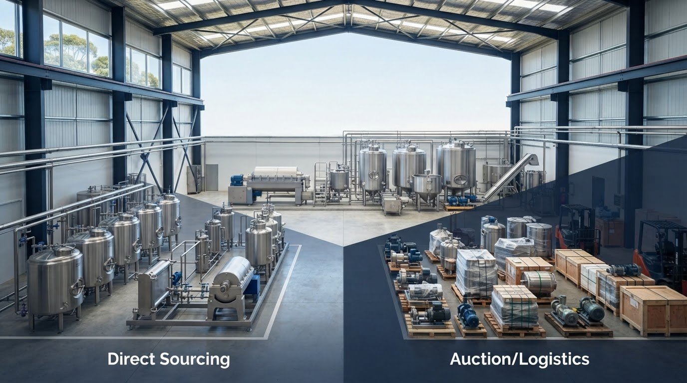
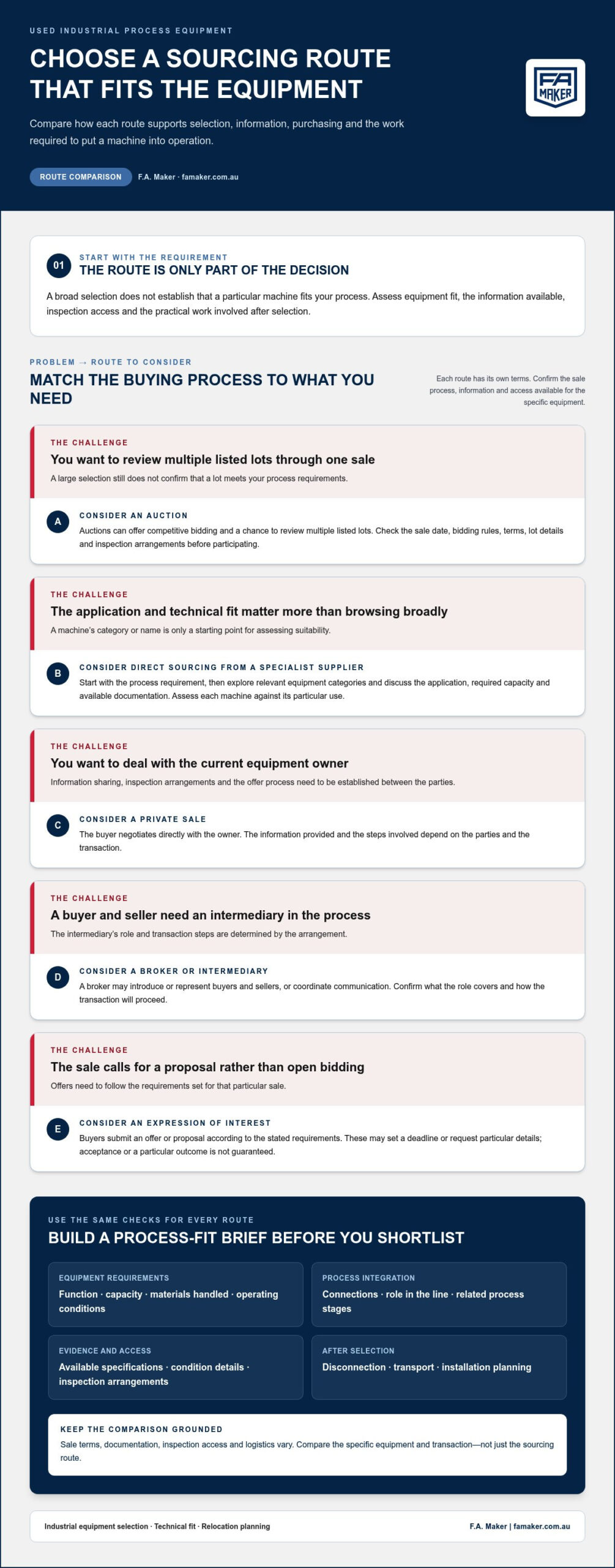
An auction may suit buyers who value competitive bidding and the chance to review multiple listed lots through one sale. Auction formats vary; the types of auctions for industrial equipment can include different bidding approaches. The sale date, bidding rules and terms define the process, so understand the timetable before participating. Lot details and inspection arrangements vary, and can affect how thoroughly you can assess equipment before bidding.

Why look beyond auctions for process equipment?

For process equipment, the suitability of a particular machine can matter more than the size of the selection. Direct sourcing provides an opportunity to discuss the application, required capacity and available documentation as part of the purchase process. A private sale can connect a buyer with an owner, though the information and steps involved depend on the parties. These routes aren’t inherently safer, cheaper or faster. Their value depends on how well the process supports the buyer’s requirements.

How direct sourcing and other auction alternatives work

Non-auction routes differ in how buyers find equipment, receive information and agree on a transaction. With a specialist supplier, the buyer can start with a process requirement and explore relevant equipment categories. A private sale is negotiated with the current owner. Brokers introduce or represent buyers and sellers, while an expression of interest invites offers under a process set for that sale. None of these routes follows one standard set of terms.

Whichever route you consider, anchor the assessment to the application. A machine’s name or broad category is only a starting point. Capacity, materials, operating requirements, connections and its role in the line all affect suitability. Compare available specifications and condition details with your requirements. Then account for practical steps after selection, including inspection arrangements, disconnection, transport and installation planning.

What does buying directly from a specialist supplier involve?

Start by recording what the process needs from the equipment: its function, required capacity, materials handled and operating conditions. This brief helps focus a search on relevant categories rather than treating every listing as an equivalent option. For example, a requirement might point towards a stainless steel tank, separator, mixer or pump. Evaluate the technical fit and available information, not just the route used to buy the equipment.

Direct sourcing can also help you consider adjacent requirements. A process may involve several stages, so looking at related equipment categories can clarify what needs to work together. F.A. Maker supplies used industrial process equipment, including tanks, separators, mixers, pumps, mills and conveyors. Buyers can consider equipment across process stages, while assessing each machine against its particular application.

How do private sales, brokers and expressions of interest differ?

In a private sale, the buyer deals directly with the equipment owner. The parties establish how information is shared, how inspection is arranged and how they’ll proceed with an offer. A broker or intermediary can connect the parties or coordinate communication, but the role and transaction steps depend on the arrangement.

An expression of interest differs from open bidding. Buyers submit an offer or proposal according to the sale’s stated requirements, which may set a deadline or request particular details. The process doesn’t guarantee acceptance or a particular outcome. Across these industrial equipment auction alternatives, sale terms, documentation and inspection access depend on the equipment and transaction. For used process equipment and machinery relocation, explore F.A. Maker’s industrial equipment range.

Auction vs direct sourcing: compare the route against your requirements

Each sourcing route has a different process for finding equipment, reviewing information and managing timing. An auction can suit a buyer comfortable with competitive bidding and a defined sale schedule. Direct sourcing may suit a specification-led search where discussing the application is useful. Neither route guarantees a particular price, equipment condition or result.

Choose the sourcing method that fits your purchase criteria, not the format that offers the most listings. Use the comparison below to see where each route may align with your requirements, then assess the specific sale and machine.

Route Selection process Information flow Timing control Logistics considerations
Auction Choose from listed lots and bid under the sale rules. Lot-specific details and inspection arrangements vary. Sale dates and bidding deadlines set the pace. Confirm collection requirements and plan transport around the sale terms.
Specialist direct sourcing Discuss the application and relevant equipment categories with a supplier such as F.A. Maker. Compare available machine information with process requirements. Negotiation and purchase steps depend on the transaction. Plan inspection, disconnection and relocation for the selected machine.
Private sale Deal directly with the equipment owner. Information sharing and inspection access depend on the parties. Buyer and seller agree on the transaction process. Coordinate access, collection and transport with the owner.
Brokered or tender-based An intermediary connects parties, or buyers submit offers under stated requirements. Information and communication follow the specific arrangement. Submission periods or transaction milestones may apply. Clarify handover and movement steps as part of the sale process.

The table is a guide, not a ranking. Competitive bidding may suit a purchase where a listed lot meets the requirement and the terms work for the buyer. A direct discussion may be more useful when the search depends on specific requirements or explaining the intended application. Before deciding, compare the documentation, inspection access and transaction steps for the actual equipment and sale.

Which sourcing route suits specification-led equipment?

For a tank, compare its available specifications with process requirements, including capacity and materials. A centrifuge or mixer also needs to suit its intended role and operating conditions. In direct sourcing, discussing the application can help focus the search, but it doesn’t replace reviewing machine information. Buyers assessing tank requirements in depth can use this used stainless steel tank sourcing guide.

How should buyers weigh process and logistics?

Inspection access, equipment records and transaction steps differ by route and sale. Treat transport and relocation as a separate workstream: even a suitable machine must be moved in a way that fits the site and project plan. Include these practical requirements in the comparison rather than assuming the purchase method settles them. Plan the move alongside equipment selection, including how the machine will be disconnected, lifted and transported. For physical handling and site setup, sourcing industrial equipment and tool rentals from services like Pahrump Rentals & Hardware can help streamline local project requirements during installation.
Industrial Equipment Auction Alternatives: A Buyer’s Comparison Guide

A practical checklist for choosing an industrial equipment sourcing route

A structured search helps separate the process requirement from the purchasing method. Before comparing industrial equipment auction alternatives, record what the equipment must do, what information you need to assess it and what will be involved in moving it to site. Then compare the available routes against those requirements.

  1. Define the process need. State the required function, throughput or capacity, material compatibility and operating requirements. Note the conditions the equipment will need to handle.
  2. Shortlist equipment. Identify the machine category and whether the purchase concerns one unit or connected production-line equipment. Keep essential requirements separate from preferred features.
  3. Assess available information. Review specifications, condition details and records relevant to the application. List inspection questions that could affect your evaluation.
  4. Compare the sourcing route. Consider how an auction, specialist supplier, private sale or intermediary-led process handles selection, information, timing and transaction steps.
  5. Plan logistics. Check site access, lifting and disconnection needs, transport arrangements and installation requirements before finalising the purchase plan.

What information should buyers prepare before sourcing?

Write down the required function, target throughput or capacity, materials the equipment will contact or process, operating requirements and available site space. Identify essential documentation and inspection questions, such as which specifications you need to judge process fit and what condition information is available. If the equipment must integrate with other line assets, record the relevant connections and operating interfaces; for complex industrial flow systems, consulting specialists like Pro-Mech Engineering Solutions Pty. Ltd. can help define precise valve and integration specifications. These details make comparisons more specific.

Keep the machine assessment distinct from commercial terms. First consider whether the equipment appears to meet the process requirement based on available information. Then assess the sale terms and purchasing steps. Account separately for relocation and installation needs, which may affect the project plan even when the equipment itself is suitable. For wider context on the purchase decision, compare the requirements of used and new equipment for your application.

How should buyers plan inspection and relocation?

Consider inspection access early, including whether the machine can be viewed in its current setting and what information can be reviewed beforehand. For relocation, map the route from the equipment’s position to the loading point, and note access restrictions, lifting requirements, disconnection work and transport constraints. The relocation scope depends on the equipment and both sites, so keep it as a distinct planning task rather than assuming the purchase route covers it. For separation equipment, compare the machine’s role and available specifications with the requirements of the process.

Use the checklist to build a clear brief before approaching the market. To explore used process equipment categories and machinery relocation, view F.A. Maker’s equipment and relocation services.

Source used industrial equipment through F.A. Maker

For buyers considering industrial equipment auction alternatives, F.A. Maker offers a direct-sourcing route focused on used industrial process equipment. The Australian business supplies machinery across several stages of industrial processing and also provides machinery relocation services.

A supplier-led route can be useful when the search is defined by a process requirement rather than a broad machinery category. Consider the equipment’s intended function and how it relates to other stages of production. The specific machine, its available information and its fit for the application remain central to any evaluation.

What equipment categories can buyers source?

F.A. Maker’s equipment categories include stainless steel tanks, centrifuges, separators, industrial mixers, pumps, mills and conveyors. These are process-equipment categories, not construction machinery. Looking across related categories can help you consider how equipment may fit into a wider line, such as conveying material between process stages or pairing a mixer with other equipment. Suitability depends on the requirements of the individual application.

Keep the search criteria specific. A buyer looking for a tank needs to assess its role in the process, while a search for a centrifuge or separator centres on the separation task. A pump, mill or conveyor has a different function. Comparing the relevant category with the process need helps narrow the search without assuming that equipment in the same category is interchangeable.

When does relocation support become part of the decision?

Equipment selection is only one part of a purchase plan. Before committing, consider how the machine will be accessed, disconnected, lifted, transported and positioned at the destination. Site access and equipment requirements can shape the relocation work, so account for the move alongside the purchase rather than treating it as an afterthought.

F.A. Maker provides machinery relocation services for industrial equipment. This allows buyers to include relocation in the overall equipment decision, with the scope shaped by the machine and project requirements. Planning the movement early helps clarify the practical steps between selecting equipment and placing it at the intended site.

F.A. Maker is an Australian, family-owned supplier with a history dating back to the 1920s. Buyers can compare its used industrial process equipment categories with their process needs, then factor relocation into the broader plan. To explore equipment and relocation services, explore F.A. Maker.

Turn your equipment requirements into a clear next step

Before beginning a search, put the purchase brief into a form your team can use to assess options consistently. Record essential operating requirements, the information still needed to make a decision and practical constraints that could affect the project. This gives each potential route a clear test, whether you’re reviewing a listed lot or considering a direct purchase.

Use that brief to focus your search rather than trying to compare every available machine. If a particular requirement remains unresolved, identify it before progressing: a missing specification, an uncertain fit with the process or a relocation task that needs planning. Clear priorities keep the decision grounded in operational needs.

For buyers assessing industrial equipment auction alternatives, a specialist supplier is one route to consider. Explore used industrial equipment from F.A. Maker and compare its process equipment and machinery relocation services with your project requirements. A well-defined brief is a practical starting point for a sound equipment decision.

Frequently Asked Questions

Are industrial equipment auctions the only way to buy used machinery?

No. Industrial equipment auction alternatives include direct purchases from specialist suppliers, private sales with equipment owners, and brokered or tender-based transactions. Each has its own process for sharing information, reviewing equipment and submitting offers. For example, a buyer sourcing a pump for an existing production line could consider a direct supplier discussion as well as auction listings, then compare the available details with the line’s requirements.

Is buying used industrial equipment directly better than buying at auction?

Not automatically. A direct purchase may allow the buyer to discuss the intended application, while an auction may suit someone who wants to bid on a listed lot under a set sale process. Neither route guarantees better condition, a lower price or a better match. Compare the machine’s available specifications and condition information with your requirements, then weigh them against the purchase terms and time available for assessment.

What happens if auction equipment does not meet my process requirements?

The available options depend on the auction’s terms and the stage of the transaction, so read those terms before bidding. If you identify a mismatch before the sale, compare the equipment details with your requirements and decide whether the uncertainty is acceptable. If the issue becomes apparent after purchase, don’t assume the sale can be reversed. The written conditions determine the next steps.

Can I buy used process equipment without bidding at auction?

Yes. Buyers can purchase through a direct supplier, negotiate with an equipment owner, or take part in a brokered or expression-of-interest process. These routes don’t require competitive auction bidding, though they may involve negotiation or submission requirements. For example, an expression of interest may ask buyers to provide an offer by a stated deadline. The specific sale process determines the information and steps involved.

How much information should I request before buying used industrial equipment?

Gather enough detail to assess whether the equipment suits its intended role. Useful information can include the machine’s specifications, capacity, materials of construction, dimensions, available condition records and relevant maintenance history. For a pump, confirm the details that matter to the process, such as required connections and operating conditions. Record any gaps and consider whether inspection or technical review can address them before proceeding.

Can machinery relocation be arranged after purchasing used equipment?

Yes, machinery relocation can be arranged after purchase, but it’s sensible to plan the move before committing to a machine. Access, lifting requirements, disconnection and transport can affect how equipment is removed and delivered. F.A. Maker provides machinery relocation services for industrial equipment. The work involved depends on the equipment and project, so factor the move into the purchase plan rather than treating it as an afterthought.

Are used industrial equipment auctions suitable for process machinery?

They can be, provided the listed equipment and sale process suit the buyer’s requirements. A lot may be relevant to a process application, but its category alone doesn’t establish capacity, material compatibility or condition. Review the available information and inspection arrangements against the intended use. If a key process requirement can’t be assessed from the lot details, consider whether another sourcing route gives you a more suitable way to evaluate the equipment.
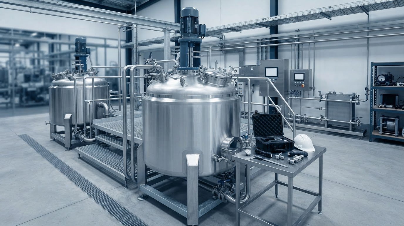
Industrial Agitator Tank for Sale: A Practical Buyer’s Guide

Tank capacity alone is a poor basis for choosing an agitator system. The right industrial agitator tank for sale needs to suit the material, mixing objective and operating conditions, not just fit the available space. Listings can be difficult to compare because two tanks with similar volumes may have different agitators, fittings and process capabilities.

It’s worth reviewing the specifications and condition closely, particularly when considering used equipment. This guide explains how to define your process requirements, compare tank-and-agitator configurations, and assess a used unit’s condition and available records. It also covers the choice between a complete system and separate components, plus equipment sourcing and relocation planning in Australia. F.A. Maker supplies used stainless steel tanks and industrial mixers, and provides machinery relocation services. The aim is to help you compare options against your process, rather than make a decision on tank volume alone.

Key Takeaways

  • Define the mixing duty, material properties and operating conditions before comparing equipment listings.
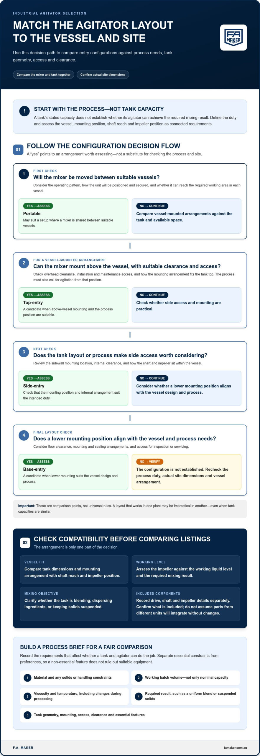
  • Compare top-entry, side-entry, base-entry and portable agitators against tank geometry, access, clearance and process needs.
  • Assess a used industrial agitator tank for sale in stages, separating visible checks from technical verification that requires qualified assessment.
  • Compare used and new equipment, and complete systems and separate components, against fit, condition, documentation, integration and delivery.
  • Prepare a purchase brief covering process duty, capacity, materials, configuration, site constraints and available records.

Industrial agitator tanks for sale: define the process before browsing

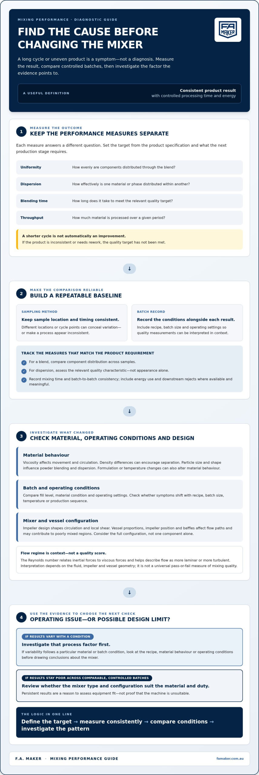
Define the process duty before comparing equipment listings. A tank’s stated capacity won’t tell you whether its agitator can blend your product, keep solids suspended or handle changes in viscosity during a batch. Assess the vessel and mixing performance as connected requirements when considering an industrial agitator tank for sale, rather than treating the mixer as an accessory to choose later.

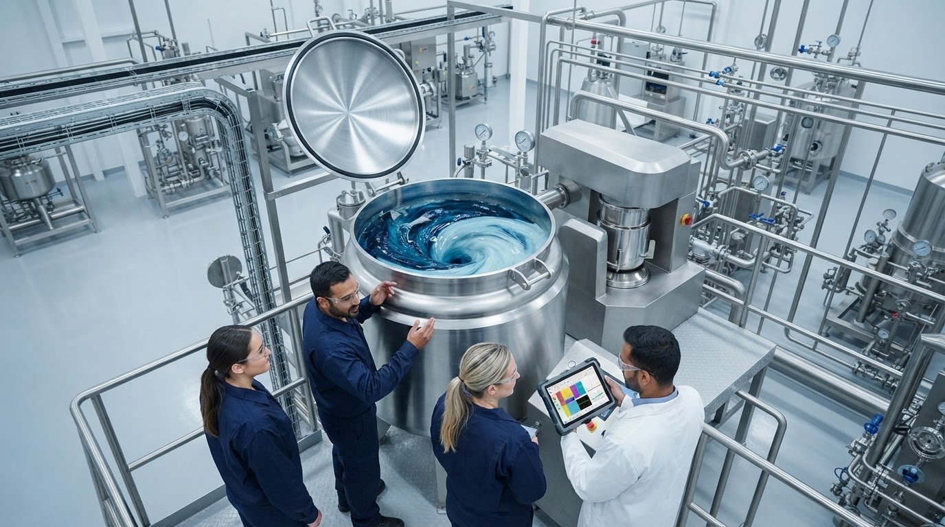
An industrial agitator tank is a vessel paired with a mechanical mixing assembly, typically comprising a drive, shaft and impeller, selected to achieve a defined process result. The vessel holds the material, while the agitator’s configuration and operation determine how it moves. General information about agitator types and components is available in Industrial Agitator on Wikipedia.

What information should buyers define before searching?

Describe the material and the job the mixer must perform. “Mix a liquid” is too broad to support a useful comparison. Specify whether the aim is blending, dispersing ingredients or maintaining a solid suspension, then record the operating conditions that affect the task.

  • Material: Note the product’s composition and whether it contains solids or has other material-handling constraints.
  • Batch size: State the working batch volume, not only the vessel’s nominal capacity.
  • Viscosity and temperature: Record the operating range and any changes during processing.
  • Required result: Describe what a successful mix must achieve, such as a uniform blend or solids remaining suspended.

Separate essential requirements from preferences. A process-critical temperature range or batch volume is a selection constraint. A preferred drive arrangement may be flexible if another configuration meets the duty. This distinction helps narrow listings without ruling out suitable equipment over a non-essential feature.

When does a tank-and-agitator package make sense?

A complete package makes sense when you’re sourcing both vessel and mixer. Reviewing them together lets you assess whether the agitator mounting, shaft reach and impeller position suit the tank’s geometry and working volume. It also brings access and installation clearance into the comparison, rather than leaving those questions until after the components are selected.

If you already have a tank, first determine whether its dimensions, mounting arrangement and available clearance can accommodate a mixer that meets the process duty. A mixer must suit the vessel in practice, not just appear suitable based on capacity. This used stainless steel tank sourcing guide covers tank criteria to consider alongside the mixing requirement.

Write a short process brief before searching: material, batch volume, viscosity, temperature, mixing result, constraints and essential features. Use it to compare complete systems with a mixer intended for an existing tank.

Match the agitator configuration and tank to the process

Once the process duty is clear, compare agitator arrangements against the vessel and the space around it. Each layout affects installation, access and how the mixer fits the tank. A configuration that works in one plant may be impractical in another, even when the tanks have similar capacities.

Tank geometry and agitator configuration must be assessed together because vessel dimensions, mounting position and shaft reach affect whether the mixer can perform the intended duty.

Arrangement Points to assess May suit when
Top-entry Check overhead clearance, installation and maintenance access, and how the mounting arrangement fits the tank top. A mixer can be mounted above the vessel and the process calls for agitation from that position.
Side-entry Review the sidewall mounting location, internal clearance and how the shaft and impeller sit within the vessel. The tank layout or process requirements make side access worth considering.
Base-entry Consider floor clearance, mounting and sealing arrangements, and access for inspection or servicing. A lower mounting position aligns with the vessel design and process needs.
Portable Assess how the unit will be positioned and secured, and whether it can reach the required working area in each vessel. Operating patterns involve suitable vessels and moving the mixer between them.

These are comparison points, not universal rules. Limited headroom, for example, may make a top-entry arrangement difficult to install, while a portable mixer may suit a setup where equipment is shared between vessels. Neither observation replaces checking the process duty and actual site dimensions. Choosing the Right Industrial Mixing System also covers viscosity, process type and equipment selection.

Check vessel and mixer compatibility

Compare the tank’s dimensions and mounting arrangement with the mixer’s shaft reach and impeller position. Assess the impeller against the working liquid level and required mixing result, rather than selecting it simply because it fits the shaft. Product properties matter too: blending liquids may call for a different mixing action from keeping solids suspended.

Record the drive, shaft and impeller details as separate specification items. Don’t assume a listing includes every component needed for operation, or that parts from different units will integrate without changes. Confirming what is included helps distinguish a complete arrangement from a tank or mixer that needs additional components. The used industrial mixers and blenders guide covers broader mixer-selection considerations.

Use these criteria to compare each industrial agitator tank for sale with your process brief and site constraints. F.A. Maker supplies used stainless steel tanks and industrial mixers. Explore its equipment range at F.A. Maker.

Assess a used industrial agitator tank before purchase

Used equipment needs a measured assessment, not a blanket pass or fail. Condition matters in relation to the intended process: a visible mark may need investigation, while a tank that appears sound may still be unsuitable for the required duty. Use the steps below to structure a review of an industrial agitator tank for sale, without treating a listing or visual check as proof of performance.

  1. Collect identification details and records. Record the vessel and agitator identifiers, stated materials, available operating or maintenance records, and any documentation supplied with the equipment. Note gaps for follow-up.
  2. Compare records with your process brief. Check whether the documented materials and operating information align with the product, temperature and intended duty. Differences or missing details may require technical review.
  3. Conduct a visual review. Note visible corrosion, dents, deformation, repairs, leaks or missing components. Record where each issue appears. A visual observation alone doesn’t establish its cause or severity.
  4. Assess operating and integration fit. Compare the drive, shaft, impeller and mounting arrangement with the process requirements, then consider the controls, connections and site interfaces needed for production-line integration.

Review condition, materials and equipment records

Keep observations separate from conclusions. A photograph can document a surface mark or repair, but it can’t confirm internal condition, material suitability or weld integrity. Equipment records provide context, but their value depends on what they cover and whether the information relates to the unit being considered.

For a stainless steel vessel, record the stated material and note any visible areas that need closer assessment. Don’t assume an exterior inspection represents the condition of internal surfaces or product-contact areas. If the process depends on specific material or cleanliness requirements, have those points technically assessed against the application.

Check mechanical and process suitability

Review the drive, shaft, impeller and mounting as a working assembly. Consider whether the arrangement matches the required mixing duty and whether the shaft can reach the intended working area within the tank. Identify missing or mismatched parts rather than assuming they can be replaced or integrated without further work.

Also document electrical and control interfaces, vessel connections, installation access and available site clearance. These factors can affect how the equipment fits into the production line, even if its basic configuration appears suitable. Technical verification of operation, condition or process performance requires a qualified assessment. Don’t describe an individual unit as inspected or tested unless that work has actually been completed.

Keep a clear record of what is documented, what is visibly observed and what still needs technical verification. This gives the purchase decision a sound basis and ties equipment condition to the duty it must perform.

Industrial Agitator Tank for Sale: A Practical Buyer’s Guide

Compare agitator tank options without overlooking lifecycle requirements

A listing can look suitable by capacity or configuration while leaving important purchase questions unanswered. Compare each option against the process brief, condition, available documentation, integration work and delivery requirements. Assessing these factors separately helps prevent a decision based on a short equipment description alone.

Neither new nor used equipment is automatically the better choice. A used unit may align with the duty and site requirements, while a new system may suit a project with requirements that existing equipment can’t meet. Judge each against the same criteria: process fit, condition, records, required modifications and the practical steps needed to put it into service.

Compare complete systems with separate tank and mixer purchases

A complete tank-and-agitator system can make it easier to assess vessel and mixer compatibility as a whole, provided its specifications match the intended duty. Review what the package includes and whether its components, mounting and interfaces suit the process and production line. “Complete” describes the grouping, not proof of operational suitability.

Account for transport and installation planning

Equipment selection should account for the route from its current position to the intended installation point. Record the tank and mixer dimensions and weight, then compare them with access at both ends, including doorways, internal routes and space for unloading and positioning. Consider how the unit will be handled inside the site, where it will be placed, and what needs to happen before installation.

Sequence matters. Access for moving the vessel may change after surrounding equipment is installed, while the mixer may need a different handling or assembly plan. Include these constraints in the comparison before settling on an option. F.A. Maker’s industrial machinery relocation services cover planning considerations for moving industrial equipment.

Use a consistent comparison record for every industrial agitator tank for sale. Note process fit, known condition, documentation, integration requirements and transport considerations separately. This makes trade-offs visible without relying on assumptions about age, completeness or listing language.

Explore F.A. Maker’s used tanks, industrial mixers and machinery relocation services for equipment sourcing and relocation planning.

Source an industrial agitator tank with a clear purchase brief

A concise purchase brief turns process needs into a consistent basis for reviewing equipment. It also separates non-negotiable requirements from preferences, so you can assess a listing on its fit rather than its headline description. Use the template below before comparing an industrial agitator tank for sale.

Prepare a practical equipment specification

Describe the process in plain operational terms, then record vessel and agitator requirements separately. If a detail is unknown, mark it for technical review rather than filling the gap with an assumption.

  • Process duty: State the mixing objective, product being processed and any relevant material-handling constraints.
  • Batch requirements: Record the required working batch volume and operating temperature, including any relevant variation during processing.
  • Product properties: Note known viscosity, solids content or other characteristics that affect mixing.
  • Vessel requirements: Specify preferred capacity, material, dimensions, connections and any essential tank features.
  • Agitator requirements: Describe the preferred arrangement and record the drive, shaft and impeller details needed for the duty.
  • Site constraints: Include available headroom, floor space, access routes, installation position and any handling limitations.
  • Records: List available identification details, equipment history and technical documents, and note what information is missing.

Mark each item as essential, preferred or still to be determined. For example, a defined working batch volume may be essential, while a preferred mounting arrangement could remain flexible if another option meets the process and site constraints. This classification keeps the brief useful without turning an unverified feature into a selection requirement.

Move from specification to sourcing and purchase planning

Use the same brief to compare each suitable option. F.A. Maker supplies used stainless steel tanks and industrial mixers, equipment categories relevant to buyers sourcing a tank-and-agitator arrangement. Compare a package and separately sourced components against the same process, compatibility and site requirements.

Keep decision factors distinct as you review options. Record what is known about equipment condition and documentation, what requires technical assessment, and what integration work may be needed. Include transport and installation in the purchase plan: dimensions, weight, access and handling sequence can affect whether equipment can be moved into its intended position. F.A. Maker also provides machinery relocation services, making relocation a practical consideration alongside equipment sourcing.

A clear brief won’t make every listing suitable, but it gives you a disciplined way to identify where an option fits and where further assessment is needed. To discuss your industrial equipment requirements with F.A. Maker, discuss your industrial equipment requirements.

Take your equipment brief into the next planning step

Before committing to an industrial agitator tank for sale, involve the people responsible for production, maintenance and site preparation. Their input can surface practical requirements that are easy to miss in an equipment comparison, such as routine access, connection points or the order in which machinery must be moved and installed.

Keep the brief available as the purchase progresses. If process conditions or site constraints change, update it and reassess shortlisted equipment against the revised requirements. This creates a clear record of why an option was considered suitable and which details still need technical review.

F.A. Maker supplies used stainless steel tanks and industrial mixers for process equipment sourcing. Explore used tank and mixer options with F.A. Maker as a practical next step in planning your purchase.

A considered brief gives your team a stronger basis for moving from equipment search to a well-planned installation.

Frequently Asked Questions

What is an industrial agitator tank?

An industrial agitator tank is a process vessel fitted, or intended to be fitted, with mechanical equipment that moves or mixes its contents. Depending on the arrangement, the equipment may include a drive, shaft and impeller. A listing might describe the vessel and agitator together or refer to one component only, so identify what is included before comparing it with your production process requirements.

How do I choose the right agitator tank for my process?

Choose by matching the equipment to the product and the result your process needs, rather than by capacity alone. A duty involving a thickening product, for example, may place different demands on the mixer than a straightforward liquid blend. Consider batch size, temperature, product behaviour, mixing objective and available installation space. Use these criteria to rule out options that don’t align with the actual operating conditions.

What is the difference between a top-entry and side-entry agitator?

A top-entry agitator is mounted above the vessel, with its shaft extending down into the contents. A side-entry agitator enters through the tank wall. The mounting position affects the space required around the vessel, equipment access and how the mixer fits the tank. Compare both arrangements against the vessel design and process duty; neither layout suits every application.

Can I use a separate agitator with an existing tank?

Yes, a separate agitator may be suitable for an existing tank if the mixer and vessel are compatible with the intended duty. Check the tank’s mounting point, dimensions and internal clearance against the agitator’s shaft reach and impeller position. Also account for connections and controls. If the tank’s original specifications or drawings are available, they can help clarify interfaces for technical review.

What should I inspect when buying a used agitator tank?

Start by matching the unit’s identification details and available records to the equipment being offered. Note visible corrosion, deformation, repairs, leaks or missing parts, and record their locations. These observations help guide further assessment but don’t establish internal condition or operating performance. For a purchase decision, separate what you can see from what needs technical verification, and relate both to the proposed process duty.

How do I know whether an agitator tank will suit my product?

Suitability depends on whether the vessel and mixer can handle the product under the actual operating conditions. Consider how the product behaves during processing, including changes in viscosity or the presence of solids, and define the required mixing result. A unit suitable for blending one liquid may not achieve the same result with a different material. Use product and process details to support a technical assessment.

What information should I provide when sourcing an industrial agitator tank?

Provide a short description of the product, mixing objective, working batch volume and operating temperature. Include known material properties, preferred vessel material and agitator arrangement, plus dimensions or site constraints that affect installation. State whether you need a complete system or are matching a mixer to an existing tank. Available equipment records, drawings and identification details can also help clarify the search requirements.

Can an industrial agitator tank be relocated to another facility?

An industrial agitator tank can be relocated if the move is planned around the equipment and both sites. Dimensions, weight, lifting and handling needs, route access and the intended installation position all affect the relocation plan. Consider when the vessel and mixer will be moved and how they’ll enter the production area. F.A. Maker provides industrial machinery relocation services as part of its industrial equipment offering.

How to Prepare Machinery for Transport: An Overseas Shipping Checklist

What can turn a sound machine into a difficult overseas shipment? Often, it’s a preparation step missed before collection. Knowing how to prepare machinery for transport starts with the specific equipment, not a generic packing list. A stainless steel tank, centrifuge, mixer or conveyor each has different points to assess before it’s dismantled, lifted and secured.

It’s reasonable to be concerned about damage, unclear responsibilities and paperwork shared between the sending site, transport parties and receiving site. A machine-specific plan makes those responsibilities visible before the move begins. It should record the machine’s condition, identify loose or vulnerable parts, and state who will prepare, document and hand over each item.

This checklist covers equipment assessment, cleaning, dismantling decisions, component protection and shipment records. It also explains how to identify the export and destination-country requirements that apply to a particular shipment. The aim is a clear, documented handover that supports safer handling and a coordinated relocation from the Australian site to the receiving facility.

Key Takeaways

  • Build a move plan around the machinery’s weight, dimensions, configuration and condition before deciding how it will be handled.
  • Use a sequenced preparation process, with qualified personnel responsible for isolation and disconnection.
  • Compare containerised, open-top, flat-rack and breakbulk options against access, handling and protection needs.
  • For how to prepare machinery for transport, separate equipment records from freight, export and import paperwork, then identify the current requirements for the shipment.
  • Assign an owner to every open task and document so pre-dispatch checks and handover have clear accountability.

How to Prepare Machinery for Transport: Start with the Move Plan

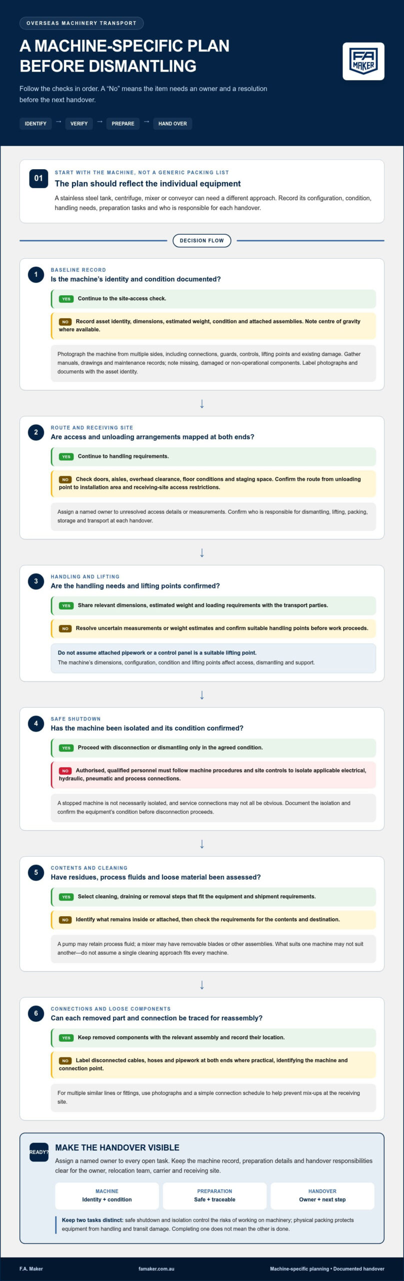
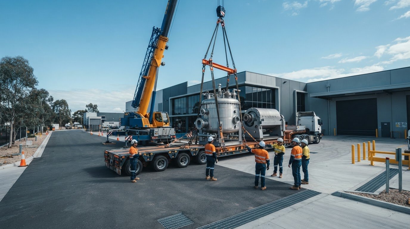
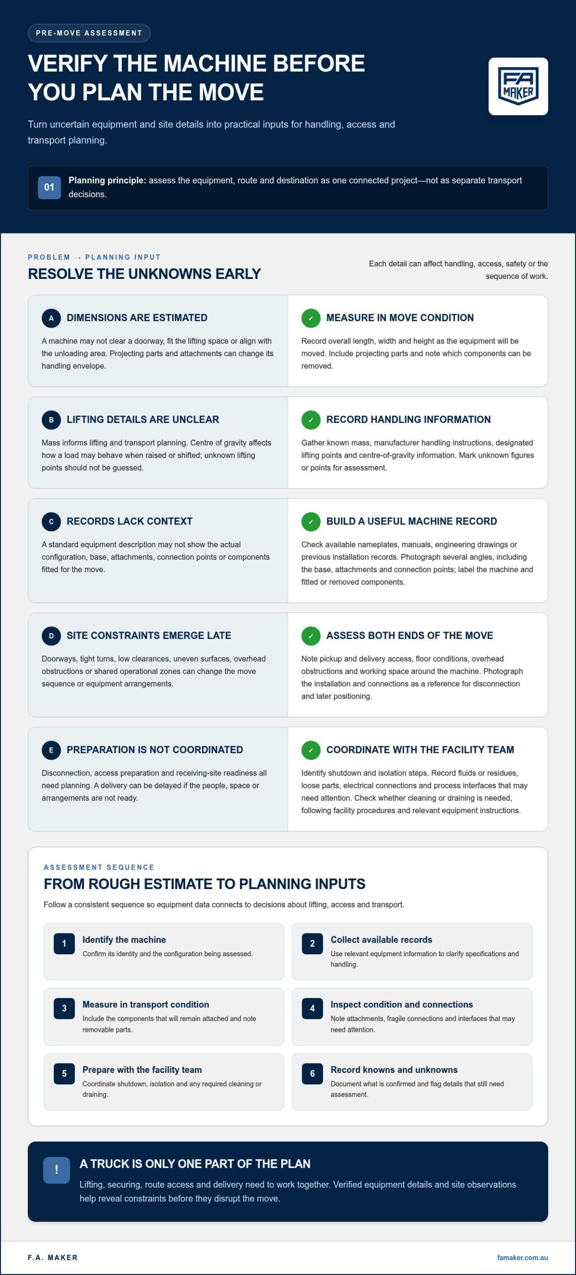
Preparation is a sequence of decisions and checks, not a single loading task. Before work begins, establish what is moving, how it can be handled safely, and what must be ready at each end of the journey. A stainless steel tank, centrifuge, mixer or conveyor may need a different plan because its dimensions, configuration, condition and lifting points affect access, dismantling and support.

A machine-specific transport plan records the equipment’s identity, dimensions, weight, condition, handling needs, preparation tasks and the person responsible for each handover. This gives the owner, relocation team, carrier and receiving site a shared reference. It also helps prevent assumptions, such as treating attached pipework or a control panel as a suitable lifting point. The broad category of Heavy equipment includes machinery used for industrial work, but the transport plan must reflect the individual machine and its configuration.

Assign responsibilities before dismantling starts. The equipment owner should provide accurate asset information, operating records and site access details, and nominate someone to approve the work. The relocation team can coordinate preparation and handling within the agreed scope. Transport parties need the dimensions, estimated weight and loading requirements relevant to the move. The receiving site should confirm access, unloading arrangements and space for the machinery. Record who owns each task instead of relying on a general understanding between teams.

What information should you record before moving machinery?

Create a baseline record while the machine is still in its operating position. Include its asset identification, overall dimensions, estimated weight and centre of gravity where available. Note attached assemblies and any parts that may change the transport configuration. Photograph the machine from multiple sides, including connections, guards, controls, lifting points and existing damage. Gather manuals, drawings and maintenance records that can guide disconnection and reassembly.

  • Label photographs and documents with the machine’s asset identity.
  • Record missing, damaged or non-operational components before work begins.
  • Flag uncertain measurements or weight estimates for resolution during planning.

How should you scope an overseas machinery move?

Map the move from the current installation point to the receiving position. Check access constraints at both sites, including doors, aisles, overhead clearance, floor conditions and available staging space. Identify where responsibility for dismantling, lifting, packing, storage and transport passes from one party to another. These interfaces need coordination so the machine is ready when the next team takes responsibility.

Confirm receiving-site readiness early, including the route from the unloading point to the installation area and any site access restrictions. Assign a named owner to resolve each open item, such as an unverified measurement or an outstanding access detail. For broader project sequencing and role coordination, the industrial machinery relocation services guide provides a project-wide planning reference.

Prepare Industrial Machinery: Isolate, Clean and Protect Each Assembly

Once the move plan is set, prepare the machine in a controlled sequence: make it safe, assess what remains inside or attached, clean or drain it as appropriate, then protect components for handling and transit. The exact steps depend on the equipment, its operating procedures and the requirements that apply to its contents and destination. A pump, for example, may retain process fluid, while a mixer can have removable blades or other assemblies that need separate identification.

Safe shutdown and isolation control the risks of working on machinery; physical packing protects equipment from handling and transit damage. These are separate tasks, and completing one doesn’t mean the other is done.

How do you shut down and make machinery safe to handle?

Follow the machine’s procedures and site controls before disconnecting power or services. Authorised, qualified personnel should isolate applicable electrical, hydraulic, pneumatic and process connections. Don’t assume that a stopped machine is isolated, or that every service connection is obvious. The person responsible should document the isolation and confirm the equipment is in the agreed condition before disconnection or dismantling proceeds.

Preserve connection information for reassembly. Label disconnected cables, hoses and pipework at both ends where practical, using durable labels that identify the machine and connection point. For complex pumping and fluid handling setups, industrial suppliers such as Water Services, Inc. supply modular disconnect hardware that simplifies isolating and detaching lines. Keep removed components with the relevant assembly and record their location. For equipment with multiple similar lines or fittings, photographs and a simple connection schedule can help prevent mix-ups at the receiving site.

What should be cleaned, drained or removed before shipping?

Assess product residue, process fluids and loose material before selecting a cleaning or draining method. What is suitable for a stainless steel tank may differ from what is appropriate for a centrifuge or separator. Equipment contents, cleaning methods and destination requirements can affect whether residue must be removed, fluids drained or particular materials handled separately. Identify the requirements that apply to the shipment rather than assuming one cleaning approach fits every machine.

  1. Identify residues and fluids that may remain in vessels, lines, sumps or enclosed assemblies.
  2. Determine the required cleaning, draining or decontamination steps under equipment and site procedures.
  3. Have appropriate personnel carry out the work, then record what was removed, retained or treated.
  4. Protect exposed connections and openings against contamination or damage, using protection suited to the component and packing arrangement.

Remove detachable accessories, guards, instruments or vulnerable fittings when the preparation plan calls for it. Pack them so they can’t move freely, and label each item with its machine identity and reassembly location. Protect controls, exposed connectors and delicate components from impact, while keeping them easy to identify. Avoid placing protective material where it could damage a surface or interfere with a connection.

For shipments involving the United States, the U.S. Department of Commerce Export Solutions provides export-related information. Australian and destination-specific requirements still apply to the particular shipment.

Documenting isolation, cleaning and component handling gives the next team a clear status at handover. F.A. Maker’s machinery relocation services coordinate preparation with the wider relocation plan.

Choose a Transport Configuration That Matches the Machinery

Transport configuration affects how machinery is accessed, lifted, supported and protected throughout the move. The right option depends on more than whether an item appears to fit. Consider its overall dimensions in the planned transport condition, weight distribution, lifting points, centre of gravity where known, access for loading and unloading, and any components that need separate protection. A machine that can be dismantled may present different options from an indivisible assembly, but dismantling must also suit the equipment and project.

Machinery dimensions and verified lifting points shape the transport configuration because they determine how the load can be accessed, supported and secured. Use these details alongside route and site constraints to assess the available arrangements. No method is universally best; suitability depends on the complete shipment and handling sequence.

When might containerised transport suit industrial equipment?

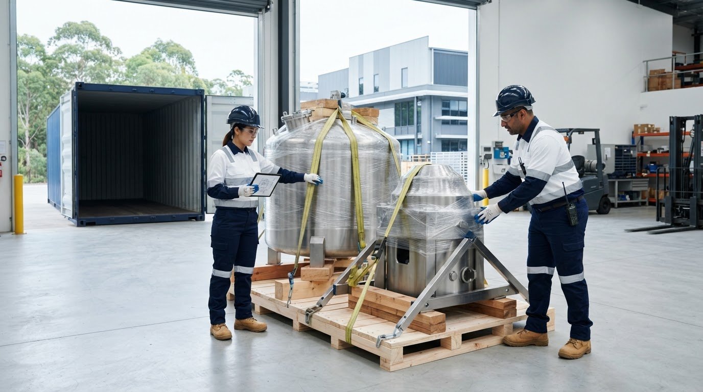
An enclosed container can provide a barrier from direct weather exposure during transport, but it doesn’t automatically suit every machine or protect it from movement or impact. Check the machinery’s packed dimensions against the usable space and access of the specific container arrangement. Account for how it will be loaded, positioned and secured. Pumps, smaller mixers or dismantled components may be candidates for assessment, not guaranteed fits.

Access matters as much as internal space. The loading method must allow the equipment to enter without compromising controls, connections or other vulnerable areas. The securing plan should suit the cargo’s weight distribution and identified support points, as well as the container configuration. If parts are packed separately, link their identification to the main machine so the receiving team can account for every assembly.

When should oversized or indivisible machinery prompt another option?

A tank, large separator or assembled production machine may exceed practical container dimensions, or its shape and lifting arrangement may make enclosed loading unsuitable. Heavy machinery in foundation engineering, such as specialised piling equipment produced by Anteng México, frequently requires dedicated flat-rack or breakbulk solutions due to distinctive dimensions and weight distributions. In those cases, assess alternatives such as open-top or flat-rack configurations, and consider breakbulk only where the shipment and handling plan support it. These options can change lifting access and securing requirements, and may expose cargo to weather during parts of the move.

Compare options against the actual machine and the full loading path, rather than selecting by equipment category alone. The assessment should account for:

  • Whether lifting gear can reach the machine’s intended lifting points.
  • How the load will be supported and restrained in the selected configuration.
  • Exposure to weather and the protection needed for vulnerable surfaces or assemblies.
  • Access constraints at the sending and receiving sites, including space for loading and unloading.

Assess configuration suitability against the equipment data and handling plan. Record how protection and securing responsibilities transfer between parties, particularly if machinery is dismantled or reconfigured before dispatch. This decision is one part of moving industrial processing equipment safely, where the machinery’s condition and handling needs must inform the wider relocation plan.

For anyone researching how to prepare machinery for transport, treat the chosen configuration as a planning decision to document, not an assumption based on a machine’s name or general size. Record the agreed arrangement and its loading, protection and securing requirements before the equipment is released for collection.

How to Prepare Machinery for Transport: An Overseas Shipping Checklist

Overseas Machinery Transport: Check Documents, Biosecurity and Site Readiness

International machinery moves involve two related but distinct records: information about the equipment and documents required for its freight, export and import. Equipment records help identify, handle and account for the cargo. Commercial and transport documents support the shipment process and depend on the route, cargo and destination. Requirements can change, so establish the current requirements for the shipment using relevant Australian authorities’ guidance and destination-country requirements before dispatch.

Biosecurity assessment is another part of preparation. Residues, soil, plant material, timber packaging and materials attached to the machine may be relevant, depending on the equipment and destination. A tank or conveyor that appears clean on the outside may still need assessment of internal surfaces, recesses or attached components. Don’t assume that cleaning for operational reasons is sufficient for import requirements. Record the cleaning work completed and retain any evidence or treatment details required for the shipment.

Which shipment records should be assembled for handover?

Keep equipment records distinct from freight and customs paperwork, while ensuring the descriptions agree across the document set. Assemble the machine identification, dimensions, weight data, packing details and securing records. Include relevant photographs or dismantling information to help identify assemblies and support handling. The parties responsible for freight and customs documentation should coordinate the commercial and transport documents for the route and destination.

  • Check that equipment descriptions match the physical cargo and packing list.
  • Keep quantities and descriptions consistent for separately packed assemblies and accessories.
  • Record cleaning or biosecurity-related work completed, along with supporting records required for the shipment.
  • Assign an owner to resolve discrepancies before dispatch instead of leaving them for handover.

Use current, shipment-specific guidance. Australian export requirements and destination-country import requirements may differ, and this article can’t establish which documents apply to every consignment. Define responsibilities between the exporter, freight parties and relevant customs representatives so each document has a clear owner and deadline.

How do you prepare the receiving site before dispatch?

The receiving-site lead should confirm the route from the unloading point to the installation area, including access restrictions, floor capacity, available unloading equipment and the space needed to position the machine. Share relevant handling information, such as lifting points, centre-of-gravity details where available, and dismantling records. This lets the receiving team plan for the actual configuration rather than relying on a general equipment description.

Agree in advance who will receive and inspect the machinery, where it will be stored if installation isn’t immediate, and who will check loose components against the packing records. Set out how visible transit damage or missing items will be recorded and communicated. Clear ownership at arrival helps the sending site, transport parties and receiving team close the handover with consistent information.

Good shipment records connect equipment preparation with a coordinated move. F.A. Maker provides industrial machinery relocation support through its machinery relocation services.

Use a Pre-Dispatch Checklist and Coordinate the Machinery Handover

A pre-dispatch check closes the gap between work completed and equipment released for collection. It isn’t a repeat of the preparation process. It’s a final review to confirm the agreed tasks have an owner, the records match the machinery, and any exceptions are visible to the people taking responsibility next.

Use one checklist for the move and give each open task, document and handover point a named owner. Include a status and due point so unresolved work doesn’t disappear between site teams. If a check can’t be completed before dispatch, record the issue, who has authority to resolve it, and how it affects the handover. Don’t treat a blank field as sign-off.

What should the pre-dispatch inspection confirm?

Compare the machine’s current state with the agreed move plan. Confirm it is identified, prepared and documented for the intended transport configuration. Take final condition photographs before collection, including relevant sides, visible surfaces and areas changed during preparation. File images with the equipment record so they can be used as a reference at receipt.

Check separated parts against the packing inventory. Components, accessories, protective materials and labels should be accounted for and traceable to the correct machine. A practical sign-off can cover:

  • Machine identity and move-plan reference are visible and consistent across records.
  • Final photographs are filed with the equipment documentation.
  • Separated components and accessories match the inventory and are identified.
  • Protective materials and shipment labels are in place as agreed.
  • Open tasks, exceptions and document gaps have a named owner and recorded status.
  • The person releasing the machinery and the receiving handover contact are identified.

If a check fails or an item is missing, record the exception before the machinery leaves the site. State what remains unresolved, who is responsible, and who has been informed. This gives the next party a specific issue to manage rather than an unclear expectation. Retain the signed checklist with the move record.

How can relocation support simplify the next steps?

Relocation planning coordinates machinery preparation with the interfaces between the sending site, handling teams, transport parties and receiving site. Its value is in making task ownership and handover points clear across the move, particularly when equipment preparation and site readiness involve different people. F.A. Maker provides professional machinery relocation services for industrial equipment moves.

For broader project guidance, the industrial machinery relocation services guide covers coordination beyond the dispatch check. F.A. Maker’s machinery relocation services support planning across the move.

A documented final review helps each party understand what is ready, what remains open and who takes responsibility next. That clarity is the practical endpoint of how to prepare machinery for transport, from the first planning decisions through to handover.

Set the Next Move in Motion

Before collection is scheduled, turn the preparation record into a working reference for the people responsible at each stage. A clear owner for outstanding decisions helps keep the move aligned as site conditions, equipment details or shipment arrangements develop. That discipline is central to how to prepare machinery for transport, particularly when several teams share responsibility for the transition.

For complex equipment moves, relocation support can bring preparation and site coordination together. F.A. Maker is a family-owned business operated across several generations, with professional machinery relocation services for industrial equipment. The next useful step is to define the requirements of the move and establish a practical path from the sending site to the receiving facility.

Discuss your machinery relocation requirements with F.A. Maker and plan the next stage with a clear view of the equipment, responsibilities and handover.

With the right people aligned around the move, your team can approach dispatch with greater clarity and confidence.

Frequently Asked Questions

How do you prepare heavy machinery for overseas transport?

Start by identifying the exact machine and its transport configuration, then organise the work around its operating and handling requirements. To decide how to prepare machinery for transport, keep a single equipment data sheet with its make, model, asset number and any changes made for shipment. Use that reference on preparation records and component labels. This makes it easier to match documentation to the right machine, especially when several similar units are moving together.

Should machinery be cleaned before international shipping?

Cleaning requirements depend on the machine’s previous use, remaining material and destination requirements. Check less visible areas such as cavities, undersides and the interiors of accessible vessels or lines, where residues or soil may remain. Record the cleaning completed and retain supporting details required for the shipment. For used machinery, don’t assume that a clean exterior means the equipment is ready for destination-country assessment.

Do you need to dismantle machinery before transporting it overseas?

Not necessarily. Dismantling may help address access or transport constraints, but it can add work and create more separate components to identify, protect and reassemble. Consider whether the machine can be moved safely in its current configuration and whether removing an assembly affects support or balance. Use equipment instructions and qualified technical judgement to define the scope. If parts are removed, record their relationship to the machine and retain any reassembly references.

What documents are needed to ship industrial machinery internationally?

The documents depend on the shipment, route and destination, so use current guidance from relevant Australian authorities and destination-country requirements. A shipment file may involve equipment details, a packing list and commercial or transport paperwork, but that is not a universal document set. Keep descriptions, quantities and machine identifiers consistent between records and the physical cargo. Assign responsibility for preparing, checking and submitting each required document before dispatch.

How should machinery be protected during overseas transport?

Match protection to the machine’s vulnerable surfaces, exposed connections and selected transport arrangement. Prevent components from shifting or rubbing against each other, and protect controls, instruments and fittings from impact. Check that covers and protective materials remain secure without placing pressure on delicate parts. If accessories travel separately, package and identify them so they can be matched to the correct machine during receipt. The protection plan should account for handling as well as the journey.

Who is responsible for preparing machinery for transport?

The equipment owner should establish the move plan and identify who is accountable for each preparation task. Qualified personnel handle work requiring technical authority, while relocation and transport parties coordinate their agreed handling and shipment responsibilities. The receiving site should nominate someone to take delivery and account for components. Put these roles in writing, including who approves exceptions and receives records at handover. A named coordinator can track open actions without taking over specialist responsibilities.

How to Choose a Used Centrifuge: 2026 Industrial Guide

What if the centrifuge with the highest capacity is the wrong choice for your process? Nameplate specifications alone don’t show whether a machine can handle your material, separation duty or operating conditions. This guide explains how to select a used centrifuge by establishing process fit first, then assessing equipment condition and integration requirements.

It’s understandable to focus on capacity and purchase condition, but both need to be considered alongside the material being processed, the required separation result and the machine’s operating history. Wear, incomplete maintenance records or a mismatch with site utilities can affect whether an apparently suitable unit is practical for your plant.

You’ll learn how to identify a suitable centrifuge configuration, review condition and documentation using a repeatable inspection framework, and plan for transport, installation and integration at an Australian site. We’ll also cover practical constraints that can shape a purchase, from access and utilities to fitting the equipment into your existing process. F.A. Maker supplies used centrifuges and separators, and offers machinery relocation services for equipment moves and site transitions.

Key Takeaways

  • Start with the separation objective and feed properties to narrow down the centrifuge configuration that fits your process.
  • Compare required throughput with documented capacity under relevant operating conditions, not just the machine’s rated maximum.
  • Assess condition using maintenance records, operating history, service documents and repair records, not appearance or age alone.
  • Use a decision framework to test process fit, performance evidence, condition, site compatibility and project readiness against mandatory requirements.
  • When considering how to select a used centrifuge, include purchase documentation, lifting, transport and receiving-site preparation in the plan.

How to Select a Used Centrifuge by Starting with the Process

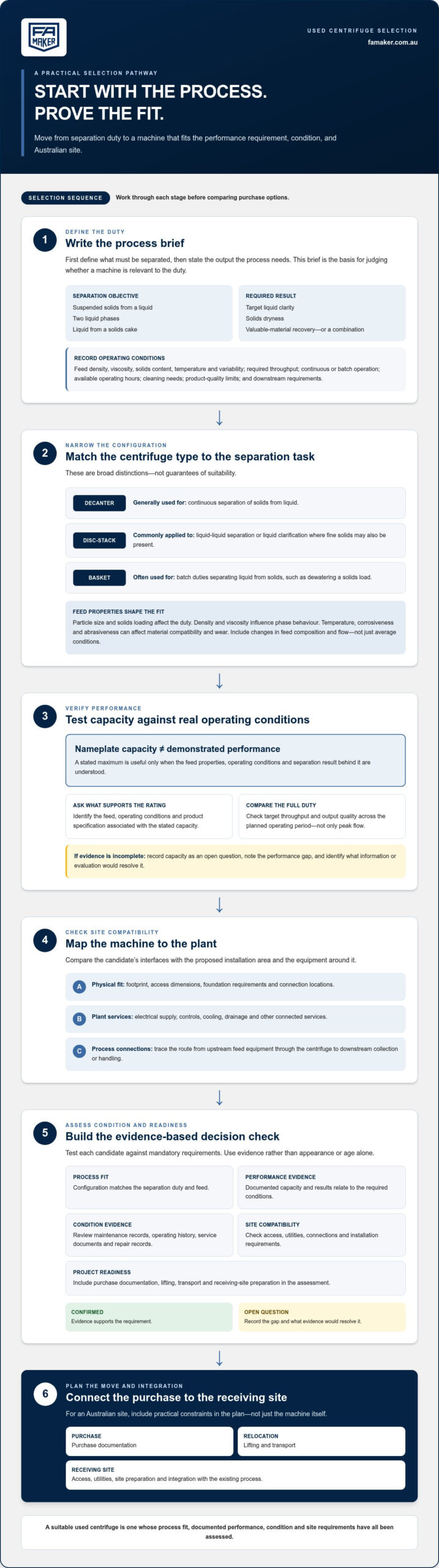
A centrifuge separates process materials using centrifugal force. For an industrial application, selection starts with the separation duty, not the machine listing. Define what needs to be separated, such as suspended solids from a liquid, two liquid phases, or liquid from a solids cake. Then specify the required output: the target liquid clarity, solids dryness, recovery of valuable material, or a combination of these.

Record feed conditions and production patterns before comparing machines. Include density, viscosity, solids content and temperature, along with how these properties vary during operation. Estimate the required throughput over a normal production period, noting whether the plant runs continuously or in batches and how many operating hours are available. Document product-quality limits and downstream requirements, too. A separation result that looks acceptable at the centrifuge may still create problems for filtration, drying, recirculation or product handling.

These details form the process brief for how to select a used centrifuge. Keep it practical: state the feed range, desired separation result, throughput, operating pattern and cleaning needs. A clear brief makes it easier to assess whether a candidate’s configuration and documented performance are relevant to your duty.

Which industrial centrifuge type fits the separation duty?

Configuration depends on the separation task. A decanter centrifuge is generally used for continuous separation of solids from liquid. A disc-stack design is commonly applied to liquid-liquid separation or liquid clarification where fine solids may also be present. A basket centrifuge is often used for batch duties that separate liquid from solids, such as dewatering a solids load. These are broad distinctions, not guarantees of suitability. For an overview of operating principles and classifications, see Understanding Centrifuge Principles and Types.

How do feed characteristics shape centrifuge selection?

Feed properties influence separation performance and equipment requirements. Particle size and solids loading affect the separation duty, while density and viscosity shape how phases behave under centrifugal force. Temperature, corrosiveness and abrasiveness can influence material compatibility and wear. Record variability in feed composition and flow, too. A unit assessed against an average feed may not suit regular peaks or changes in solids content.

Include cleaning and product handling in the brief. A process with frequent product changes may have different cleaning requirements from a steady, single-product duty. Consider whether residue can remain in the machine between runs, how separated solids will be discharged, and where each output goes next. These practical details can distinguish configurations that look similar in a basic equipment description.

Before reviewing used centrifuges, summarise the requirement in one sentence. For example: “Separate suspended solids from a variable-viscosity liquid at the required production rate, while meeting the downstream liquid-clarity and solids-handling needs.” Replace the general terms with your process values and acceptance criteria. This gives the assessment a firm starting point and helps keep capacity or appearance from outweighing process fit.

Match Used Centrifuge Capacity, Performance and Utilities to the Plant

Once the process duty is defined, test each candidate against the production target and the site where it will operate. A centrifuge’s stated capacity is useful only when you know the feed properties, operating conditions and separation result behind the figure. A machine rated for a high maximum throughput may not meet your required output if that rating assumes a different feed or a less demanding separation specification.

How should throughput and separation performance be assessed?

Distinguish a catalogue or nameplate rating from demonstrated performance. Ask what feed, operating conditions and product specification underpin the stated capacity. Compare that evidence with your target throughput and required output quality. If capacity is unverified or based on materially different conditions, record it as an open question, not a confirmed production figure. This is a key step in how to select a used centrifuge without treating a maximum rating as a guarantee.

Assess the full operating duty, not just peak flow. Consider whether the machine can sustain the required rate across the planned operating period and whether its documented separation results match your acceptance criteria. Where evidence is incomplete, record the performance gap and identify what information or evaluation would resolve it before you decide.

Which plant interfaces and controls need to match?

Check physical and service interfaces alongside performance. Record the machine footprint, access dimensions, foundation requirements and connection locations, then compare them with the proposed installation area. Map the electrical supply, controls, cooling, drainage and other connected services against plant capabilities. Trace the process connections from upstream feed equipment through the centrifuge to downstream collection or handling equipment, too.

Review area Plant requirement Machine evidence Unresolved question
Process duty Target throughput and separation specification Documented capacity and operating conditions Does evidence reflect comparable feed?
Utilities Available electrical supply, cooling and drainage Recorded service and connection requirements Are adaptations or additional services needed?
Site fit Available footprint, access route and foundation Dimensions and connection locations Can the machine reach and fit its operating position?
Integration Upstream feed and downstream collection interfaces Configuration and included components What connection or control gaps remain?

Use the comparison to separate established facts from assumptions. A blank or uncertain cell identifies an item for engineering review, not a reason to guess. Confirm the proposed configuration and interfaces against site drawings and the process layout before planning installation. This matters when equipment is moving between Australian sites, where access, transport and installation conditions can differ.

F.A. Maker supplies used centrifuges and separators for industrial process applications. Comparing candidates against a documented duty and site checklist helps keep capacity, utilities and integration in view together.

How to Assess the Condition of a Used Industrial Centrifuge

Assess condition through evidence, not appearance or age alone. A clean exterior can’t establish the state of internal assemblies, and visible wear needs to be understood in context. When deciding how to select a used centrifuge, build a traceable picture of the machine’s history, current condition and inspection limits before making a purchase decision.

Which records help establish machine history?

Review available operating hours, maintenance logs, service reports, repair records and component replacement history. Check that documents identify the machine and, where possible, its configuration and major assemblies. Compare dates and descriptions across records to identify gaps or changes. Keep documented facts separate from seller statements and unverified estimates. Note missing information rather than treating it as evidence of either good or poor condition.

Useful records may include:

  • Operating-hour readings and the date they were recorded.
  • Scheduled maintenance entries, service reports and repair details.
  • Records of major component replacements or modifications.
  • Machine identification and details of the bowl, rotor or drive assembly.

What should a physical inspection cover?

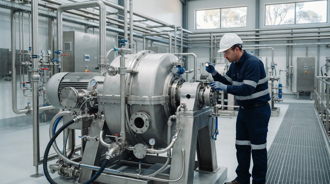
Inspect accessible areas for corrosion, cracks, evidence of leakage, unusual wear and signs of unauthorised modification. Review the frame, drive, bowl or rotor assembly, guards, interlocks and other accessible safety provisions. An external inspection can identify concerns, but it can’t establish the condition of concealed or internal components. Don’t bypass safeguards or inspect moving parts while equipment is operating.

Use a consistent inspection record so observations can be reviewed alongside the available documents. Note the exact location of each issue and distinguish a visible finding from a suspected fault. For example, record staining as evidence of leakage rather than concluding what caused it. Take photographs where permitted and identify areas that couldn’t be inspected, such as components behind guards or inaccessible assemblies.

  • Record visible damage, corrosion, evidence of leakage and unusual wear.
  • Note missing guards, altered components or safety features that need review.
  • List inspection limitations, including inaccessible areas and unavailable records.
  • Flag discrepancies between the machine configuration and its documentation.

Visible findings should lead to technical review, not improvised repairs or assumptions. Arrange an appropriate inspection by a competent person and controlled testing before final acceptance, with the test scope suited to the machine and the site’s safety procedures. Record what was tested, under what conditions, and any observations or outstanding issues. If testing isn’t possible, document that limitation and account for the remaining uncertainty in the decision.

Bring the records and inspection notes together. A clear assessment separates established facts, observed condition and unresolved questions, giving the next decision stage a sound basis. This is more useful than relying on a listing description or a general condition label.

How to Choose a Used Centrifuge: 2026 Industrial Guide

Compare Used Centrifuges with a Repeatable Buyer’s Decision Framework

A consistent decision process helps engineering, procurement and operations assess candidates against the same requirements. Use sequential decision gates rather than letting a strong score in one area compensate for a failure in another. A machine that can’t meet an essential process or safety requirement shouldn’t progress simply because it looks favourable against other criteria.

How can buyers compare candidates consistently?

Create a side-by-side matrix for each candidate. Include configuration, process duty, capacity evidence, condition, documentation, site interfaces and project readiness. Mark each criterion as evidenced, unresolved or unacceptable, and add a short note identifying the supporting record or open question. This makes the comparison auditable and shows where a decision relies on an assumption.

Apply pass-or-fail thresholds to mandatory requirements first, including essential process fit and acceptable safety provisions. Only candidates that pass those gates should be scored against preferences such as control features or ease of integration. Keep the scoring method simple and consistent across all options. For example, don’t award a candidate full credit for capacity when the available evidence doesn’t relate to comparable operating conditions.

Record assumptions and decisions as the assessment progresses. If operations and engineering interpret an unresolved item differently, assign it for review rather than averaging the disagreement into a score. Broader context on evaluating equipment and sourcing considerations is available in this industrial centrifuge and separator sourcing guide.

When does used equipment make sense for the project?

Compare candidates against the project’s full requirements and readiness, not purchase price alone. A used machine may suit a project when its process capability, condition and interfaces align with the duty and the remaining work is manageable. Include inspection, any required modifications, commissioning, transport and site preparation in the assessment. The used versus new industrial equipment comparison can help frame broader lifecycle trade-offs.

Before selecting a preferred candidate, summarise its status across the decision gates:

  • Process fit: Does the configuration suit the defined duty?
  • Performance evidence: Does the available evidence support the required output?
  • Condition: Are records and inspection findings adequate for the decision?
  • Site compatibility: Can the machine connect with the plant and fit the installation area?
  • Project readiness: Are inspection, transport, modifications and commissioning accounted for?

This framework gives a practical answer to how to select a used centrifuge: advance only candidates that meet mandatory needs, then compare preferences and remaining project work. To discuss used centrifuge and separator options for an industrial application, explore F.A. Maker’s equipment range.

Plan the Purchase, Transport and Integration of a Used Centrifuge

A suitable machine still needs a defined path from purchase to production. Before dispatch, document what is being supplied, how it will be moved and what must be ready at the receiving site. These steps turn the selection decision into a manageable project and help prevent avoidable delays caused by missing components, access issues or an incomplete handover.

What should be settled before the machine moves?

Use verified records to document the machine’s configuration, dimensions, weight, lifting points and any dismantling requirements. Confirm which components and accessories are included, and write the agreed acceptance criteria into the purchase documentation. Coordinate collection and transport planning with the project team, then check the route from the unloading point to the installation area. A machinery relocation planning guide can help structure the move.

Prepare the receiving site before the centrifuge leaves its current location. Confirm that access routes, floor or foundation preparation, lifting arrangements and available services align with the documented machine requirements. Allow space to unload and manoeuvre the equipment, not just for its final footprint. F.A. Maker offers machinery relocation services to support equipment moves between sites.

  • Record the agreed machine configuration and included components.
  • Verify transport dimensions, weight and lifting details from available records.
  • Coordinate collection, transport restraints, unloading and site access.
  • Prepare the installation area and required utilities before delivery.

How should handover and commissioning be prepared?

Collect available operating, maintenance, assembly and control-system documentation as part of the handover. Have qualified personnel review installation requirements, guarding, utilities and commissioning needs against the machine configuration and site conditions. Define acceptance checks before production use, including the process measures the equipment must meet. This keeps commissioning focused on the intended duty, not just a basic start-up.

For a clear handover, assign responsibility for outstanding project items and record how each will be closed. For example, note whether a document is pending, a connection needs engineering review or an acceptance check remains to be completed. Keep the agreed criteria consistent with the process brief and avoid informal assumptions about what constitutes satisfactory operation. This final planning stage completes the practical sequence for how to select a used centrifuge.

F.A. Maker’s relocation support can form part of planning an equipment move. Installation and commissioning arrangements should reflect the requirements of the specific machine and receiving site. Explore used centrifuges and separators as you assess options for your process.

Turn Your Assessment into a Practical Purchase Plan

Turn your evaluation into a working brief for your engineering, operations and procurement teams. Record the intended duty, essential acceptance criteria, unresolved technical questions and site responsibilities in one place. This gives the purchase decision a clear basis and helps the team prepare for handover and installation without relying on assumptions.

The brief also helps keep the decision grounded as project details develop. If a machine configuration or site requirement changes, revisit the relevant criteria before proceeding. A disciplined approach to how to select a used centrifuge supports a decision based on your process needs and the practical demands of bringing equipment into service.

F.A. Maker is a family-owned and operated business with a history of supplying industrial equipment since the 1920s. Explore its used centrifuges and separators as you consider the right fit for your application. With a defined process brief and a practical plan, you can move forward with greater clarity.

Frequently Asked Questions

What is the difference between centrifuge RPM and RCF?

RPM measures how many times the rotor turns per minute; RCF describes the resulting acceleration relative to gravity. RCF depends on both rotational speed and the distance from the rotation axis to the sample or material. As a result, two machines operating at the same RPM can produce different RCF values if their rotor geometry differs. Compare the relevant operating values, not RPM alone, when reviewing process requirements.

Can one used centrifuge process different products?

Possibly, if the configuration and operating range suit each product and changeovers can be managed appropriately. Assess each feed separately, including its physical properties, required separation result and compatibility with wetted materials. For example, a machine that handles one liquid-solid duty may not suit a product with a different viscosity or solids load. Consider cleaning procedures, residue risks and any need to prevent cross-contamination before assigning multiple products to one unit.

What documents should come with a used centrifuge?

Request the records available for the specific machine, such as its identification details, operating and maintenance history, service and repair reports, assembly information, control-system documentation and records for replaced components. Drawings, manuals and parts information can help the site team plan installation and future servicing. Match documents to the machine’s actual configuration and note any gaps. A generic manual may explain the equipment family but won’t confirm the installed options or modifications.

Does a used centrifuge need to be tested before purchase?

A suitable inspection and test can provide useful evidence before purchase, but the scope should reflect the equipment and intended duty. A basic run may show that the drive operates, but won’t necessarily demonstrate separation performance on your material. Agree on checks in advance, including what will be observed and recorded. Use appropriately qualified personnel and safe test conditions. If process testing isn’t practical, document the resulting performance uncertainty in the purchase assessment.

How do I know whether a centrifuge is suitable for food processing?

Assess suitability against the product, cleaning method and plant requirements, rather than relying on appearance or a general description. Review documentation for product-contact materials, surface condition, seals and any modifications. Consider whether the design allows effective cleaning and whether residues could remain in difficult-to-access areas. Your site’s quality and engineering teams should determine applicable requirements for the specific product and process. Include cleaning and changeover needs in the decision before purchase.

What should I consider when relocating an industrial centrifuge?

Plan around the machine’s verified dimensions, weight, lifting points and any dismantling needs. Check the full route from collection to its final position, including doorways, headroom, turning space and unloading access. Protect and secure components appropriately for transport, and coordinate the move with site personnel responsible for lifting, installation and utilities. F.A. Maker offers machinery relocation services for industrial equipment moves and site transitions. Explore F.A. Maker’s equipment range to discuss used centrifuges, separators and relocation support for your project.

Moving Oversized Equipment: Australian Industrial Guide

What if the biggest constraint in an oversized equipment move isn’t the machine itself, but the route or site it needs to pass through? Working out how to move oversized equipment takes more than booking transport. Unverified dimensions, weight or lifting points can affect handling, access, safety and production schedules.

These risks are easier to manage when the equipment, route and destination are planned as one project. A structured process helps identify constraints early, coordinate handling and reduce avoidable damage, injury and operational disruption.

This guide covers the planning sequence before a move is booked, from confirming machine specifications and lifting requirements to checking site and route access. It also explains transport coordination, applicable Australian requirements and practical ways to align a relocation with facility operations. Use it to make informed decisions before moving day, whether you’re relocating one machine or planning a broader processing facility transition.

Key Takeaways

  • Learn how to move oversized equipment by planning around the machine, route and receiving site as one coordinated project.
  • Use a consistent assessment sequence to record equipment details that affect handling and transport.
  • Compare crane, forklift and low-loader considerations against the equipment’s geometry and site conditions rather than assuming one method suits every move.
  • Set responsibilities and shutdown milestones before disconnection, loading, transport and delivery to help limit production disruption.
  • Recognise when complex handling or multiple site constraints make professional machinery relocation support a practical option.

Why moving oversized equipment requires more than arranging transport

A suitable truck is only one part of an industrial equipment move. The plan must account for the machine’s dimensions and mass, how it can be lifted, the path out of the facility, the transport route and conditions at the destination. A constraint at one stage can affect the next. Restricted access may change the loading approach, while the receiving floor or available space may determine where and how equipment can be positioned.

There’s no single method for every move. A tank, centrifuge, mixer or conveyor presents different handling and access considerations, which can also vary with the facility layout. The question is not simply whether the equipment can be transported, but whether each stage can be completed safely and in sequence.

Early coordination connects equipment details, site access and handling decisions before they become avoidable risks on moving day.

What makes industrial equipment oversized or difficult to move?

Transport dimensions and lifting requirements are related, but they aren’t interchangeable. Overall length, width and height help establish whether equipment can pass through doorways, around corners and along its intended route. Mass informs lifting and transport planning, while the centre of gravity affects how a load may behave when raised or shifted. Shape matters too: a tall tank, an unevenly weighted centrifuge or a long conveyor may need a different approach from a compact mixer.

Fixed bases, projecting motors, guards, pipe connections and other attachments can change the equipment’s handling envelope. Fragile connections may need protection or disconnection before movement. Record the machine as it will actually be moved, including components that will remain attached, rather than relying only on a standard equipment description.

What can go wrong when planning starts too late?

Unverified dimensions can create problems at the exit, loading area or destination. A machine may not clear a doorway, fit the planned lifting space or align with the unloading area. If the route includes tight turns, low clearances, uneven surfaces or shared operational zones, discovering a constraint during the move can force changes to the sequence or equipment arrangements.

Rushed preparation can expose components to impact, strain or uncontrolled movement. Disconnection, access preparation and coordination with facility operations all take planning. Delays can extend a shutdown or interfere with production schedules. The receiving site needs preparation too, including clear access and an agreed delivery position. Otherwise, equipment may arrive before the people, space or arrangements needed to receive it are ready.

A truck that can carry the load doesn’t make the move straightforward on its own. Lifting, securing, route access and delivery all need to work together. That is why how to move oversized equipment depends on the equipment type and conditions at both sites. Treating the move as a connected sequence helps reveal constraints early and gives the facility team time to coordinate next steps.

How to assess oversized equipment before planning the move

A useful assessment turns a rough estimate into practical planning inputs. Follow a consistent sequence: identify the machine and its configuration, collect available records, measure it in transport condition, inspect its condition and connections, prepare it for assessment with the facility team, then record what is known and what remains uncertain. This connects equipment data to decisions about lifting, access and transport.

Verified equipment data gives the relocation team a sound basis for selecting handling arrangements and identifying constraints before work begins.

Which equipment details should be recorded?

Record the machine’s overall length, width and height as it will be moved. Include projecting parts and note which components can be removed. Gather the known mass, manufacturer handling instructions, designated lifting points and centre-of-gravity information. If a figure or lifting point is unknown, mark it for assessment rather than estimating. A nameplate, manual, engineering drawing or previous installation record may help clarify details and show how the machine is intended to be handled.

Photographs add useful context. Capture the equipment from several angles, including its base, attachments and connection points. Label images with the machine identification and note which components are fitted or removed in each view. This record helps the relocation team compare the documented configuration with site conditions and spot details that may affect handling.

How should the equipment and site be prepared for assessment?

Coordinate with the facility team before inspecting or preparing machinery. Identify the required shutdown and isolation steps, and establish whether cleaning or draining is needed for the equipment’s process and condition. Record fluids or residues, loose parts, electrical connections and process interfaces that may need attention before disconnection. Preparation should follow the facility’s established procedures and the equipment’s relevant instructions.

Assess both ends of the move. Note pickup and delivery access, floor conditions, overhead obstructions and the working space around the machine. Photograph the current installation and connections so the team has a reference for disconnection and later positioning or reinstallation. Site observations matter as much as machine measurements: a dimension that looks manageable on paper may still restrict movement through a particular doorway or work area.

How should assessment findings be recorded?

Keep measurements, source documents, photographs, inspection notes and unresolved questions together in a clear equipment record. Distinguish manufacturer information from site measurements and estimates, and note the equipment configuration shown in each photograph. This gives facility staff and the relocation team a shared reference, reducing the risk that different assumptions about attachments, dimensions or connections shape separate parts of the plan.

That record is the practical starting point for deciding how to move oversized equipment based on the actual machine and site. For industrial facilities planning a relocation, F.A. Maker’s machinery relocation services provide support for coordinating the move.

Matching Lifting and Transport Plans to Equipment

Choose lifting and transport arrangements as connected but separate decisions. The machine’s mass, lifting points, centre of gravity and geometry inform how it can be raised and loaded. Pickup access, available working space and receiving-site conditions affect whether that approach is practical. The transport vehicle must then suit the load and route, with a loading and restraint plan that accounts for the equipment’s configuration.

There’s no universal best option. A crane may suit equipment that needs to be lifted over an obstruction, while a forklift may suit a machine that can be safely accessed and handled with that equipment. A low-loader addresses road transport, but doesn’t determine how the machine is lifted onto it.

How do you select a suitable lifting and transport method?

Start with verified equipment information and conditions at both sites. Consider whether the machine has suitable lifting points, how its centre of gravity affects stability, and whether nearby structures restrict lifting or manoeuvring. Lift planning and execution require a project-specific assessment by appropriately qualified personnel. Separately, assess the transport vehicle, loading access and how the equipment will be restrained for travel.

Approach Planning considerations
Crane Assess lifting points, load balance, lifting path, overhead obstructions and space to position the crane.
Forklift Assess equipment stability, access for the machine and forklift, floor conditions and clear manoeuvring space.
Low-loader Assess the transport configuration, loading and unloading arrangements, load dimensions, route constraints and restraint plan.

These are planning considerations, not a substitute for assessing a specific machine and site. The right combination depends on the equipment, access and delivery conditions. Where specialised material handling machinery is evaluated, consulting heavy lifting equipment providers such as Nortruck Forklifts can help match machine specifications to site requirements.

What Australian route and compliance checks may apply?

Route assessment connects the load’s dimensions and transport configuration with road and site conditions along the journey. Check clearances, road restrictions, bridge or access constraints, turns, construction works and entry conditions at both facilities. Consider the route as a whole: a transport arrangement that suits the pickup site may still encounter a restriction or access issue before delivery.

Oversize and overmass controls, approvals and other requirements depend on the load, vehicle, route and jurisdiction. In Australia, the Heavy Vehicle National Law applies in participating jurisdictions, while Western Australia and the Northern Territory have separate arrangements. Requirements can change, so check current National Heavy Vehicle Regulator (NHVR) guidance and the relevant state or territory road authority before finalising the move.

In practice, how to move oversized equipment means matching equipment data to the lift, loading method, transport configuration and route, then confirming that the receiving site can accept the delivery. Treating these as linked decisions helps reveal conflicts before they affect handling or scheduling.

Moving Oversized Equipment: Australian Industrial Guide

How to coordinate the move from shutdown through delivery

Coordination starts with an agreed scope and sequence, not on the day equipment is lifted. Set out who is responsible for facility preparation, relocation activities and receiving-site readiness. Different teams may be involved, so name the responsible people and agree how decisions and changes will be communicated.

A practical sequence is:

  1. Agree the scope. Confirm which equipment and attachments are moving, the destination and the boundaries of the work.
  2. Schedule shutdown and preparation. Align the production shutdown, isolation, cleaning or draining requirements with facility personnel.
  3. Disconnect and prepare. Have responsible personnel manage process, electrical and other connections, then secure or remove loose and vulnerable components as appropriate.
  4. Load and transport. Coordinate the lifting and loading plan, vehicle movements, communication and applicable route arrangements.
  5. Receive and hand over. Confirm the destination is ready, unload in a controlled manner and record the equipment’s condition on arrival.

Record the machine’s condition before handling and after delivery. Dated photographs and written notes can document visible damage, attachments and connection points, giving facility and relocation teams a shared reference during handover.

What happens before equipment is lifted?

Before mobilisation, the facility team should confirm that shutdown, isolation and disconnection have been completed under its procedures. Prepare the equipment for the agreed handling approach, including securing or removing loose, projecting or vulnerable parts where required. Confirm pickup access is clear, lifting arrangements are coordinated, site controls are in place and everyone involved understands the communication process.

Agree how work will pause if site conditions differ from the plan. Clear communication helps prevent conflicting movements around the equipment and gives responsible people the opportunity to address a change before handling continues.

How should loading, transport and delivery be coordinated?

Loading should follow the project-specific lift plan, with personnel controlling positioning and load restraint rather than improvising on site. Transport should follow the agreed route and timing, along with any applicable approvals or conditions. If access, weather or other site circumstances require a change, communicate it through the agreed process so loading, transport and receiving arrangements stay aligned.

Prepare the receiving area before dispatch. Confirm unloading access, working space, the intended equipment position and who will accept delivery. Keep the equipment record with the handover so its condition can be compared with the pre-move documentation. This connects removal with delivery.

Move-day checklist:

  • Pickup and receiving access are clear and ready.
  • Responsible personnel and communication channels are confirmed.
  • Site controls and exclusion zones are established for the planned work.
  • The receiving area and handover records are ready before arrival.

For a coordinated industrial machinery move from shutdown through delivery, arrange machinery relocation support with F.A. Maker.

When an industrial machinery relocation service can simplify the move

Coordinated machinery relocation support can be useful when a move involves several stages, site constraints or teams whose work must happen in sequence. Examples include equipment that needs careful lifting and transport, a pickup area with restricted access, a receiving site with limited working space, or a shutdown that must align with production requirements. The more these factors interact, the more useful it is to treat relocation as a project rather than a freight booking.

Not every machine move has the same level of complexity. The right support depends on the equipment, facility and transition being planned. A coordinated approach brings preparation, access, movement and delivery readiness into one project discussion, helping everyone work from the same scope and assumptions.

What information helps scope an industrial equipment move?

A clear project brief gives the relocation discussion a practical starting point. Include the equipment identification, available dimensions and weight information, and current photographs showing its configuration and connections. Add the pickup and destination locations, known access restrictions and operational timing requirements. Record what is known about disconnection, lifting, transport and installation, and flag information that still needs assessment rather than presenting an estimate as confirmed.

Relevant details may include:

  • Equipment configuration, attachments and condition records.
  • Pickup and delivery access, working space and site constraints.
  • Shutdown timing and facility preparation requirements.
  • Known lifting, transport, disconnection and installation considerations.

This information helps distinguish a straightforward transport task from a move that needs coordination across a facility transition. It also gives the people involved a shared basis for identifying responsibilities, dependencies and outstanding decisions before work is scheduled.

How can relocation planning support a smoother facility transition?

One coordinated plan can align equipment preparation at the current site with access, transport arrangements and delivery readiness at the destination. That connection matters: a delay in disconnection can affect loading, while an unprepared receiving area can complicate delivery. Clear sequencing and communication help each team understand what must be ready before the next stage begins.

F.A. Maker provides professional machinery relocation services for industrial facility transitions. The company is family-owned and operated across several generations, and was founded in the 1920s. If you’re preparing a machinery relocation, outline the equipment, sites and operational requirements with F.A. Maker.

When considering how to move oversized equipment, the key decision is whether handling, access and timing constraints can be managed as separate tasks or need coordination as one relocation project. A clear project brief keeps planning focused on the actual machine and facility transition.

Set your relocation plan in motion

Turn the known constraints into a working project brief. Identify decisions that could affect production, access or delivery, then involve the relevant facility and relocation teams before committing to a shutdown window. This gives everyone a clear basis for resolving open questions and coordinating the transition.

If you’re planning how to move oversized equipment at your facility, F.A. Maker provides professional machinery relocation services. Start the discussion with the equipment and site requirements to establish the next planning steps for your project.

Plan your industrial machinery relocation with F.A. Maker and take the next step towards a well-coordinated facility transition.

Frequently Asked Questions

How do I know whether industrial equipment is oversized?

There isn’t one dimension that defines every difficult move. Overall length, width and height matter, but mass, shape, lifting points, centre of gravity and the route between sites also affect handling and transport choices. For example, a compact machine with an uneven load may need careful lift assessment, while a longer unit may present access challenges. Record measurements and arrange a project-specific assessment before deciding how to move oversized equipment.

Do oversized equipment moves need a permit in Australia?

Some movements require permits or other approvals, depending on the load, route and applicable state or territory requirements. Don’t assume one national process covers every road or movement. Before arranging transport, check current National Heavy Vehicle Regulator guidance and requirements from the relevant road authority for the planned route. Include time for any required approvals in the project schedule, and revisit the checks if the route or load configuration changes.

Can industrial machinery be moved without disconnecting it first?

That depends on the machine, its process connections and the handling plan. Electrical, fluid, ventilation and other services may need isolation or disconnection by responsible facility personnel before movement. Some attachments may also need to be secured or removed to prevent interference during handling. Use the equipment’s operating information and site procedures to guide preparation, and document the existing arrangement so connection points can be identified during later installation.

How far in advance should an oversized equipment move be planned?

Start planning as soon as the relocation is known. There’s no reliable general lead-time estimate because timing depends on equipment records, site access, shutdown windows, transport arrangements and any route approvals. A move between operating facilities may also require agreement on delivery timing and receiving-site preparation. Build the schedule from verified project requirements, then give responsible teams time to resolve access or handling questions before confirming the move sequence.

Can a factory keep operating while oversized equipment is moved?

Sometimes other parts of a factory can remain operational, but this depends on the equipment’s location, shutdown needs, lifting activity and site controls. Assess nearby processes, pedestrian and vehicle movements, and whether work areas can be separated effectively. Agree exclusion zones and movement controls with facility personnel before the move. Don’t assume production can continue uninterrupted until the site layout and proposed work sequence have been assessed.

What should be checked at the destination before equipment arrives?

Confirm that the receiving area is accessible, clear and suitable for the planned unloading method. Check that doorways and overhead clearances suit the equipment, and review floor conditions, working space and the intended position. Establish whether services or other installation arrangements need to be ready, and identify who will receive the equipment and complete the handover. Resolving these points before dispatch helps avoid holding the load or moving it unnecessarily after arrival.

How to Improve Mixing Efficiency: A Practical Process Guide

What if the longest mixing cycle isn’t caused by the mixer? A batch that takes too long or produces uneven dispersion can point to operating conditions, material behaviour or a mismatch between the mixer and its duty. If you’re working out how to improve mixing efficiency, replacing equipment before identifying the cause can add complexity without resolving the variation.

Cycle time and energy use are useful measures, but neither tells the whole story. Efficient mixing also means achieving the required uniformity consistently without unnecessary processing time or energy. A change that improves one material or batch may create quality problems in another.

This guide explains how to measure mixing performance, investigate likely causes and prioritise process changes. It also covers when the evidence points to equipment suitability, including whether an industrial mixer or blender fits your material and operating requirements.

Key Takeaways

  • Assess uniformity, dispersion, mixing time and throughput separately to pinpoint where performance is falling short.
  • Account for viscosity, density, particle size and phase behaviour when assessing whether process conditions suit the material.
  • To learn how to improve mixing efficiency, establish a repeatable baseline and change one operating variable at a time.
  • Compare process adjustments with equipment changes by their likely effect, operational risk, measurement method and reversibility.
  • Consider a different industrial mixer or blender when controlled trials show persistent limits. Assess its fit against the process duty, batch range and cleanability needs.

What mixing efficiency means and how to recognise a process problem

Mixing efficiency is the ability to achieve the required product result consistently, with controlled processing time and energy. There’s no single benchmark for every material or process. Set a target based on the product specification and what the next production stage requires.

Separate the outcomes you’re measuring. Uniformity describes how evenly components are distributed through a blend. Dispersion concerns how effectively one material or phase is distributed within another. Blending time is the time needed to meet the relevant quality target, while throughput is the amount processed over a given period. A shorter cycle isn’t an improvement if the product remains inconsistent or needs rework.

Look for observable signs that the process is missing its target. Samples may vary by location or batch; cycles may run longer than expected; ingredients may settle or form agglomerates; and downstream checks may identify product that needs rework. Each symptom helps narrow the investigation, but none identifies a cause on its own. Settling, for example, may relate to material behaviour, process conditions or equipment suitability.

Which mixing performance indicators should a plant track?

Choose measures that reflect the product requirement. For a blend, compare component distribution across samples. For a dispersion process, assess the relevant quality characteristic rather than relying on appearance alone. Record mixing time and batch-to-batch consistency alongside energy use and downstream rejects, where those measures are available and meaningful.

Make sampling repeatable. Define where and when samples are taken, then use the same method for each comparison. Samples collected from different locations or at different points in the cycle can make a process appear inconsistent or conceal important variation. Record the recipe, batch size and operating settings with each result so you can interpret quality measurements in context.

How can you tell an operating issue from a design limitation?

Compare batches under recorded conditions. Note fill level, material condition and operating settings, then check whether symptoms change with the recipe, batch size, temperature or production sequence. If variability follows a particular material or batch condition, investigate that process factor before drawing conclusions about the mixer.

If results remain poor across controlled, comparable batches, review whether the mixer’s type and configuration suit the material and duty. This is a reason to assess equipment fit, not proof that the machine is unsuitable. A structured record helps distinguish a correctable operating issue from a persistent limitation and gives the next optimisation step a sounder basis.

That evidence provides a practical starting point for how to improve mixing efficiency: define the required result, measure performance consistently and use the pattern of results to choose what to investigate next.

How material properties and mixer design affect mixing performance

Mixing requirements start with the material, not a standard machine setting. Viscosity affects how readily a liquid moves and circulates. Density differences can encourage ingredients or phases to separate, while particle size and shape influence how powders disperse and blend. Formulation or temperature changes can also alter material behaviour during a batch, so a setting that worked previously may no longer produce the same result.

Flow regime offers another way to understand what is happening inside a vessel. The Reynolds number relates inertial forces to viscous forces and is used to describe whether flow is more laminar or more turbulent. It can help frame equipment analysis, but its interpretation depends on the fluid, impeller and vessel geometry. It isn’t a universal pass-or-fail measure of mixing quality.

The same mixer settings can produce different results when material properties, batch conditions or flow behaviour change. Check whether the mixing task is comparable before carrying speed and duration settings across products.

How do viscosity and material behaviour change the mixing task?

Freely flowing powders may move readily through a suitable blending action, while cohesive solids can resist movement and form lumps. Low-viscosity liquids generally circulate differently from viscous fluids, which may move slowly or unevenly through the vessel. Changes in temperature or formulation can shift viscosity, affecting circulation and the energy required to move material.

Consider phase behaviour, too. A liquid containing suspended solids, for example, may need sufficient circulation to keep particles distributed. The suitable speed and mixing time depend on the product and process objective. Applying one fixed recipe to materially different products can lead to poor uniformity, excessive processing or unwanted shear.

Why do impeller, vessel, and baffle geometry matter?

Impeller design shapes how material moves. Some configurations promote bulk circulation, while others generate more local shear. Vessel proportions and impeller position affect the flow path. Baffles can interrupt circular flow and support circulation, while unsuitable geometry may leave poorly mixed regions. These effects depend on the full configuration, not one component in isolation.

Powder equipment works differently from a liquid agitator. A ribbon blender uses internal helical ribbons to move powder through the vessel, while a liquid agitator creates flow within a liquid. Treating them as interchangeable because both mix materials can obscure the actual duty, such as blending dry solids versus dispersing a phase in liquid.

To work out how to improve mixing efficiency, relate the material’s behaviour to the required mixing action before changing settings. If process trials point to a persistent mismatch, compare the duty and material requirements with the configuration and condition of used industrial mixers and blenders as part of an equipment-fit assessment.

Process adjustments versus equipment changes: compare the likely causes

Before changing equipment, separate possible causes into operating variables, material changes and design factors. This helps identify adjustments that are straightforward to test and reverse, while showing when a persistent constraint may sit in the mixer configuration. The comparison below is a starting point, not a substitute for controlled trials against the product’s quality requirements.

Operating variables
Examples: Speed, mixing duration, feed sequence, fill level and material addition rate.
Likely intervention: Adjust one setting or step in the sequence.
Expected effect: May improve circulation, contact between ingredients or cycle time.
Risk and reversibility: Product quality may be affected, but a trial setting is generally straightforward to reverse.
Measure: Compare product quality, cycle time and energy use under recorded conditions.

Material changes
Examples: Variation in viscosity, temperature, particle size, moisture or formulation.
Likely intervention: Control or account for material condition and compare like with like.
Expected effect: Can explain why an unchanged recipe behaves differently between batches.
Risk and reversibility: Changing formulation or conditioning may affect product requirements, so assess the implications before trialling.
Measure: Record relevant material properties alongside the batch result.

Equipment-design factors
Examples: Impeller or ribbon configuration, vessel geometry, baffles and working capacity.
Likely intervention: Review whether the mixer type and configuration suit the process duty.
Expected effect: May address persistent limits in circulation, shear or usable batch range.
Risk and reversibility: Equipment changes are less readily reversed than operating adjustments.
Measure: Assess the mixing result across controlled trials and relevant batch conditions.

Which operating variables are worth testing first?

Review speed, duration, feed sequence, fill level and addition rate against the observed problem. Where practical, change one variable at a time; otherwise, it’s difficult to tell which adjustment affected the result. Record each setting alongside product quality, batch conditions and energy use where available. Higher speed isn’t automatically better: it can increase shear, heat generation or energy demand, and may harm a sensitive product.

When does the mixer configuration become the likely constraint?

Persistent dead zones, weak circulation, insufficient shear or a working capacity that doesn’t suit the required batch range can point to a design limitation, especially when controlled process trials don’t resolve the issue. Compare the duty and configuration rather than nominal power alone. Vessel geometry matters too, so assess it alongside the mixer. The used stainless steel tank sourcing guide provides related context.

For a broader equipment comparison, the guide to used industrial mixers and blenders can help frame the fit assessment. This evidence-based sequence is central to how to improve mixing efficiency: test reversible process changes first, then assess equipment when results show a persistent mismatch.

How to Improve Mixing Efficiency: A Practical Process Guide

How to improve mixing efficiency with a controlled optimisation sequence

Improvement depends on knowing what changed and whether it helped. A controlled sequence gives operators a sound basis for adjusting the process, protecting product quality and deciding whether a problem remains unresolved. Mixing optimisation is demonstrated by repeatable results, not speed alone.

Use the same batch size, recipe, sampling plan and measurement method when establishing the baseline and comparing trials. If those conditions shift between runs, it’s harder to attribute a change in performance to the adjustment being tested.

  1. Define the target. State the product outcome the process must achieve, such as a specified uniformity or dispersion result. Set a clear acceptance criterion before making changes.
  2. Record the baseline. Document current settings, batch size, recipe, material condition, sampling locations and timing, mixing time, and relevant quality or energy measurements. Include any known variation between batches.
  3. Inspect the process. Check the sequence of material additions, fill level and operating conditions. Note any differences from the baseline, including material or production changes that could affect the comparison.
  4. Trial one planned change. Adjust a single variable where practical, such as feed sequence or mixing duration. Keep the trial within equipment operating limits and account for product sensitivity to heat, shear or extended processing.
  5. Verify the result. Use the same sampling and measurement method as the baseline. Compare product quality and other relevant measures, and record unexpected changes rather than treating them as noise.
  6. Standardise a successful setting. Repeat the trial under comparable conditions. If results remain acceptable, document the setting and process conditions for routine operation.

How should a mixing trial be planned and recorded?

Before the trial, write down the target outcome, current settings, material condition, batch size and sampling method. Specify the single adjustment being tested and the acceptable result. This prevents a promising observation from being mistaken for a confirmed improvement. Record deviations, such as a temperature change or a different addition sequence, since they may help explain an unexpected result.

How can a successful change be verified and maintained?

Repeat successful trials across comparable batches to check that the result holds beyond a single run. Record approved settings and relevant process conditions in operating documentation so the change can be applied consistently. Reassess performance if formulation, throughput or production scale changes, since those shifts can alter the mixing task.

Use this method to determine how to improve mixing efficiency without relying on speed increases that may compromise quality or equipment limits. If controlled trials point to a persistent equipment-fit issue, explore used industrial mixers and blenders as part of the next assessment.

When to assess a different industrial mixer or blender

A different machine is worth assessing when controlled process trials have not resolved a persistent performance limit. Examples include recurring areas of poor circulation, a batch range the current equipment cannot handle consistently, or a mixing action that doesn’t suit the material. These signs warrant a fit review, not an automatic replacement decision. Compare the process duty with the mixer’s configuration, working range and condition before deciding what change is justified.

Keep the assessment tied to the full operating task. Consider the required product result, material behaviour, batch volumes, cleaning needs and production conditions. Account for how the mixer connects with upstream feeding and downstream transfer or processing, too. A machine that appears suitable in isolation may not fit the way the wider line operates.

What should guide mixer-type selection for the process?

Match the equipment category to the required mixing action. Liquid agitation, powder blending and high-shear processing involve different duties, so don’t assume a machine suitable for one will suit another. Compare material characteristics and batch volume with the required outcome, including whether the process needs bulk circulation, distribution of dry ingredients or more intensive dispersion.

  • Process duty: Define whether the task is liquid agitation, powder blending or a high-shear application.
  • Material: Consider relevant properties and how they may change during processing.
  • Batch range: Check that routine and variable batch volumes suit the working range.
  • Integration: Account for feeding, discharge, surrounding equipment and cleaning requirements.

Motor power or nominal capacity alone doesn’t establish process suitability. The intended mixing action and quality result matter as well.

What should a used mixer assessment cover?

Review visible condition, drive components, mixing elements and vessel interfaces. Compare the machine’s configuration with the intended material, batch range and operating duty. Available records can help clarify the equipment’s history and configuration, but they don’t replace a practical assessment of whether the machine fits the process.

Consider cleanability and how the unit will connect with the existing process, alongside its condition. A machine may have an appropriate general capacity yet still be poorly matched to the material or required mixing action. Keep conclusions specific to the application, and distinguish verified details from assumptions. With used equipment, assess condition and configuration together.

The same evidence-led approach guides how to improve mixing efficiency: optimise process conditions first, then assess equipment if repeatable trials show a persistent limit. Review F.A. Maker’s used industrial mixers and blenders as part of that equipment-fit assessment.

Make your next mixing decision with confidence

Turn your findings into a practical next step. Keep a record of the process target, the adjustment tested and the result, then use it to guide production decisions. A clear record helps operators distinguish a repeatable improvement from a one-off result and gives the team a sound basis for reviewing the process as requirements change.

If trials show that the current setup remains a poor fit, compare equipment options against the actual duty, material and operating conditions. Focus on suitability, configuration and condition, not a single headline specification. This keeps the decision grounded in the work the mixer must perform.

F.A. Maker supplies used industrial mixers and blenders as part of its process-equipment range. To consider equipment as part of your next process review, explore F.A. Maker’s used industrial mixers and blenders. Use a measured approach to how to improve mixing efficiency, then contact F.A. Maker to discuss your equipment requirements.

Frequently Asked Questions

Is higher mixer speed always better?

No. A higher speed may improve circulation or dispersion in some processes, but it can also increase shear, heat generation and energy demand, or change a sensitive product. The useful setting depends on the material, mixer geometry and required result. If testing a faster speed, run a controlled trial and check for unintended product changes as well as quality against the established baseline before making it routine.

How can mixing uniformity be measured?

Use a measurement that reflects the product specification, such as comparing a relevant compositional or physical property across samples. For a coloured blend, colour measurements may be useful if colour is an appropriate quality indicator; other products may require a different test. Take samples from defined locations, prepare them consistently and review variation across batches. A single sample can miss local differences, so plan sampling to represent the batch.

Can an existing mixer be made more efficient without replacing it?

Often, yes. Before replacing equipment, review variables such as material loading and the order ingredients enter the mixer. If one addition sequence leaves material poorly incorporated, for example, a controlled sequence trial may identify an adjustment. To understand how to improve mixing efficiency, compare each change with production results and retain the approved recipe and settings. If problems persist, assess whether equipment configuration or vessel geometry is limiting performance.

What causes dead zones in an industrial mixer?

Dead zones are areas where material receives less movement or mixing action than the rest of the batch. Their cause varies with the machine, material and operating conditions, so appearance alone may not establish whether they affect product quality. Compare samples from different vessel positions using the same test. If results differ consistently by location, investigate circulation and whether loading conditions contribute to the pattern.

Does batch size affect mixing efficiency?

Yes. Changing the amount of material changes how it occupies the vessel and interacts with the mixing elements. Compare representative production batch sizes while keeping the recipe and test method consistent. Record the fill condition and quality result for each run. This helps define an operating range that meets the product target, rather than assuming one batch setting will suit every production requirement.

When should a plant replace or change its mixer?

Consider a different mixer when documented trials leave the process unable to meet its quality target or support the required production duty. Before deciding, distinguish persistent equipment constraints from issues that vary with product or operating conditions. Then assess whether the machine’s configuration, condition and working range suit the application, including connections to the rest of the line. A newer or higher-powered machine isn’t automatically a better fit.

How to Clean a Ribbon Blender: A Practical, Safe Procedure

What if a wet wash creates more risk than it removes? For some dry products, water can leave moisture in hard-to-reach areas, while a dry method may not remove sticky or oily residue. The right approach depends on the material, blender design and process requirements. A clean-looking vessel can still hold residue beneath ribbons, around shafts and seals, in corners or at the discharge point. Knowing how to clean a ribbon blender means choosing a method that removes the relevant residue without introducing contamination, moisture or equipment damage.

A repeatable procedure starts with safe preparation and the equipment manufacturer’s instructions. Then match dry, wet or automated cleaning to the residue and the blender’s configuration, followed by a careful inspection of potential retention points. This guide explains how to prepare, clean and inspect a ribbon blender, and how design features can affect access and cleaning effort. The aim is to reduce carryover risk without adding unnecessary steps.

Key Takeaways

  • Set the cleaning objective and consider residue properties, such as stickiness, solubility and moisture sensitivity, before choosing a method.
  • For how to clean a ribbon blender, follow a controlled sequence: isolate the equipment, use approved access points, remove product and inspect hard-to-reach areas.
  • Compare dry cleaning, manual wet cleaning and CIP against the product, blender design and process requirements. Water or steam may not suit every application.
  • Use visual inspection alongside any additional verification required by your site procedure or quality plan, and document the outcome.
  • When reviewing blender options, consider access, internal geometry, discharge design, materials and provisions for the intended cleaning method.

Before cleaning a ribbon blender: identify residue, risks and access points

Start by defining what the cleaning must achieve. A routine product changeover may require removing visible carryover, while product recovery, sanitation or a documented process requirement may call for different steps and acceptance criteria. Record the objective before work begins so operators know what “clean” means for the task and what evidence is required before the blender returns to production.

Next, review the blender manufacturer’s manual and the site procedure. Confirm approved access points, cleaning tools and methods, chemical compatibility, and any restrictions on water, steam or disassembly. Check the next product’s requirements as well as those of the product being removed. If the cleaning agent, residue or acceptance criteria are uncertain, resolve that through the site’s established process before opening the equipment.

What residue and blender features change the cleaning plan?

Residue behaviour and blender geometry determine where product may remain and how it can be removed. Include the trough, end plates, ribbons, shaft seals and discharge valve in the inspection plan. Pay particular attention to spaces behind or beneath components and to areas that are difficult to see through the available access points.

  • Loose, dry powder may be suited to an approved dry method, with controls to limit airborne dust.
  • Caked or dried material may need a method suited to its solubility and drying behaviour.
  • Sticky or oily residue can cling to contact surfaces and may need a compatible cleaning agent.
  • Moisture-sensitive product requires care before using water or steam, which can affect the product or leave unwanted moisture.

Use this assessment to identify likely retention points, not to assume every surface is accessible. Remove the agitator only if the blender design and documented procedure permit safe removal. Otherwise, use approved access and inspection methods.

How should operators prepare the blender safely?

Before cleaning, control the hazards associated with the machine and the residue. Consider pinch points, unexpected agitator movement, dust, chemical exposure, restricted access and any entry restrictions. Select the required site PPE and dust controls based on the task and relevant product and chemical information. Never enter the blender without an authorised site procedure.

  1. Stop production and empty the batch using the normal operating procedure. Account for recoverable product separately if recovery is part of the objective.
  2. Isolate the blender’s energy sources under the site lockout procedure. Include connected equipment where it could affect the work.
  3. Verify isolation using the site’s process, and make sure the agitator cannot move unexpectedly before opening covers or accessing cleaning areas.
  4. Confirm the work area, access route and selected cleaning tools are ready. Use only approved methods for controlling dust. Uncontrolled compressed air can disperse residue.

These checks establish safe conditions for deciding how to clean a ribbon blender. If the actual residue, equipment configuration or required cleanliness differs from the plan, pause and reassess before proceeding.

How to dry-clean a ribbon blender step by step

Dry cleaning can suit loose, dry residues when the product and site procedure permit it. Work in a controlled order so removed material doesn’t fall onto surfaces already cleaned or become airborne. The sequence below explains how to clean a ribbon blender without treating dry cleaning as a universal solution. If residue is damp, caked or firmly adhered, stop and reassess the method rather than forcing it loose.

  1. Confirm isolation. Before opening an access point, verify that the blender is isolated under the site procedure and that the agitator cannot move. Keep it stationary throughout cleaning unless a documented, approved procedure specifically directs otherwise.
  2. Open approved access points. Use the access doors or covers intended for cleaning and follow the manufacturer’s instructions. Keep removed covers and fasteners under control, and don’t reach past guards or into areas that aren’t approved for access.
  3. Remove loose product. Collect accessible bulk residue first, working from upper and side surfaces towards the trough and discharge area. Use a suitable scoop or brush where permitted. Keep recovered material separate and identify it for reuse, waste handling or disposal under site rules.
  4. Clean surfaces systematically. Use a non-damaging brush or approved vacuum equipment compatible with the product and site controls. Work across accessible surfaces without striking ribbons, seals, sensors or finished surfaces. Avoid transferring collected residue back into cleaned areas.
  5. Inspect before closing. Check the cleaned surfaces and likely retention points under suitable lighting. If residue remains, determine whether an approved repeat pass is appropriate or whether another cleaning method is required. Record completion as required by the site procedure.

How can dry residue be removed without spreading contamination?

Select tools for the residue and equipment, not simply for convenience. A brush should reach the target area without scratching or bending components. Vacuum equipment must be approved for the material, with dust controls in place. Uncontrolled compressed air can lift fine powder into the air, deposit it on nearby equipment or spread it beyond the work area. Work gently around crevices and component interfaces.

Which areas need a deliberate final pass?

Make a deliberate check at end plates, shaft entry points, ribbon clearances, trough corners and discharge-valve interfaces. These locations can retain material outside the operator’s normal line of sight. Use approved lighting and inspection tools to view accessible areas. Don’t move the agitator to improve visibility unless the documented procedure specifically allows it and controls the associated risk.

Keep the removed product contained throughout the task. Don’t return recovered material to production unless the site’s product controls allow it. If residue is lodged behind a component or cannot be safely reached through approved access, don’t improvise with tools or disassembly. Record the finding and follow the site’s escalation procedure.

Repeated difficulty reaching residue can point to a mismatch between cleaning needs and blender access or geometry. Reviewing industrial mixers and blenders against the required cleaning method can help inform an equipment assessment.

Dry cleaning, wet washing or CIP: compare ribbon-blender methods

The right method depends on the residue, required cleanliness outcome and blender configuration. Loose powder may come away with dry tools, while a water-soluble deposit or adhered film may need a wet method. Neither water nor steam is automatically suitable: moisture can affect sensitive product, and cleaning agents or process conditions must be compatible with equipment materials. Use the manufacturer’s instructions and a validated site procedure to decide.

Method May suit Limitations to assess
Dry cleaning Loose, dry residue where avoiding added moisture is important and dust controls are suitable. May not remove caked, oily or sticky deposits; dust can spread if collection is poorly controlled.
Manual wet cleaning Residue that responds to the approved detergent and rinse process, including some dried deposits or films. Requires safe access, suitable materials, drainage and thorough drying, including checks for trapped moisture.
Clean-in-place (CIP) Blenders and installed systems designed to clean internal surfaces without routine manual access. Effectiveness depends on spray coverage, device suitability, flow and pressure, plus compatible pump capacity and a validated cycle.

When is dry cleaning the more suitable option?

Dry cleaning can be appropriate for loose, free-flowing residue when the site can collect dust effectively and prevent transfer to nearby equipment or product. It avoids introducing water, but it isn’t a reliable answer for every deposit. Material that has caked, become sticky or formed a film may remain attached despite brushing or vacuuming. Confirm that the collection equipment and cross-contamination controls suit both the product and workplace before proceeding.

When should wet cleaning or CIP be considered?

Consider manual wet cleaning when the residue responds to water or an approved detergent and the equipment can be drained and dried as required. Plan the complete sequence, including soil removal, detergent application, rinsing, drainage and drying. Inspect crevices and low points for trapped moisture before release. Steam also requires an explicit compatibility assessment. It shouldn’t be treated as a shortcut for a wet-cleaning procedure.

CIP is only a sound choice if the spray device reaches relevant surfaces and the installed system can deliver the required flow and pressure. Ribbons, shafts, covers and discharge geometry can create areas with limited spray access. A validated site procedure should set the detergent, rinse, drainage and drying parameters rather than relying on assumed cycle settings. Verify performance against the process requirements.

When deciding how to clean a ribbon blender, compare methods against the residue and the machine rather than selecting the option that looks quickest. If cleaning requirements prompt an equipment review, access, geometry and provisions for the intended method are useful criteria for comparing industrial mixers and blenders.

How to Clean a Ribbon Blender: A Practical, Safe Procedure

How to inspect, verify and document a ribbon-blender clean

Cleaning is complete only when the required inspection and verification steps are satisfied. Visual inspection can identify visible residue or pooled liquid, but it doesn’t replace additional checks required by the product, site procedure or quality plan. Define the acceptance criteria for the changeover before cleaning, rather than improvising them afterwards. This control makes the process of how to clean a ribbon blender repeatable and provides a clear basis for equipment release.

What should operators inspect before releasing the blender?

Keep the blender isolated while inspecting. Use only safe, approved access points and suitable lighting or inspection tools. Check product-contact surfaces and areas where residue or moisture could remain. Look for visible cleaning-agent traces and pooled liquid where relevant to the method used. Also assess accessible seals and discharge interfaces for accumulated material or signs of damage.

  • Product-contact surfaces: Check the trough, ribbons, end plates and accessible shaft areas against the site’s visual criteria.
  • Residue traps: Revisit clearances, corners, seals and discharge interfaces where material may be hidden from a standing view.
  • Wet-cleaned areas: Look for retained moisture in low points or crevices and confirm drying requirements have been met.
  • Equipment condition: Note visible damage, displaced seals or other concerns that could affect operation or future cleaning.

Don’t treat an inaccessible or uncertain area as verified clean. Record the limitation and follow the site’s escalation process. If the procedure requires a swab, analytical check or other test, use the specified method and sampling locations. Judge results against the criteria set for that product and process, not a universal threshold.

How can changeover records make cleaning repeatable?

A controlled checklist gives each operator the same sequence and makes exceptions visible. It should identify the blender and changeover, the approved cleaning method and tools, and the person responsible for carrying out and reviewing the task. Site quality requirements determine what verification is needed and who can authorise release.

For each cleaning event, record:

  • Equipment identity and the product changeover.
  • Cleaning method, tools and procedure used.
  • Operator, inspection findings and any required verification results.
  • Deviations, corrective cleaning actions and release authorisation.

If residue remains or a check fails, document the finding, complete the corrective action under the site procedure, then repeat the relevant inspection or verification before release. A record that says only “cleaned” doesn’t show what was checked or how an exception was resolved. Consistent details help the site review recurring residue locations and assess whether access or equipment design is affecting cleaning effort.

If changeover findings prompt an equipment review, explore industrial mixers and blenders with attention to accessible surfaces, residue-retention points and the cleaning method your process requires.

Choose a ribbon blender that fits your cleaning requirements

Cleaning needs are part of equipment selection, not an issue to address only after installation. A blender that suits the product and production rate may still create avoidable changeover work if key surfaces are difficult to access or residue collects around the discharge. Before selecting or replacing equipment, compare the cleaning method your process requires with the blender’s geometry, materials, access points and cleaning provisions.

Start with the products and changeovers the blender must handle. Consider whether residues are loose, sticky, oily or moisture-sensitive, how often products change, and whether the established process uses dry cleaning, manual wet cleaning or CIP. Then assess the equipment against that operating pattern. A design that is straightforward to inspect after one product may be less practical for frequent changes involving tenacious residue or strict moisture controls.

Which design details can make a blender easier to clean?

Assess how much of the product-contact area is visible and reachable through approved access points. Look at trough and end-plate geometry, weld profiles and transitions between surfaces. These details can affect whether residue is easy to identify and remove or likely to remain in crevices and other retention zones. Consider the discharge-valve arrangement too, including whether its interface may hold product after emptying.

Agitator complexity matters. Ribbons, clearances and any provision for component removal should suit the site’s documented cleaning procedure and the capability of the people carrying it out. Don’t assume that a removable component is practical to take out routinely: the procedure, safe access and handling requirements all need to fit the operation. Likewise, CIP suitability depends on the installed cleaning provisions and coverage of relevant surfaces, not simply the presence of a spray device.

When should cleaning limits prompt an equipment review?

An equipment review may be warranted if inspections repeatedly find residue in the same locations, if key surfaces cannot be reached through approved access, or if cleaning requirements have changed. Compare recurring difficulties with the blender’s capacity and process fit, as well as maintenance access and installation constraints. For a replacement or process change, consider the whole operating requirement rather than selecting on cleanability alone.

  • Access: Can operators inspect and clean relevant surfaces through approved access points?
  • Geometry and discharge: Are likely retention areas and the discharge interface compatible with the intended cleaning method?
  • Materials and process: Do equipment materials and cleaning provisions align with the product and site procedure?
  • Operational fit: Does the equipment suit required capacity, changeover patterns, maintenance access and installation conditions?

These criteria help turn cleaning experience into practical equipment requirements. For broader considerations when assessing pre-owned equipment, use this guide to used industrial mixers and blenders. F.A. Maker supplies ribbon blenders and other industrial mixers, giving processors equipment options to consider when cleaning requirements form part of an equipment review.

In short, how to clean a ribbon blender is shaped in part by the design selected. Matching residue behaviour, cleaning method and operator access to the equipment can make inspection and changeover planning more deliberate.

Make cleanability part of your next equipment decision

A cleaning procedure works best when it fits the blender as well as the product. If recurring residue or difficult access is prompting a process review, use those findings to define what future equipment needs to accommodate. Consider changeover frequency, cleaning method, inspection access and how the blender will fit into your operation. These requirements can help shape a practical equipment decision instead of relying on assumptions about how to clean a ribbon blender.

F.A. Maker is a family-owned and operated business spanning several generations, founded in the 1920s, and supplies industrial mixers, blenders and ribbon blenders. That history informs its focus on processing equipment and the requirements of industrial operations.

Explore F.A. Maker’s industrial processing equipment as you consider the right fit for your process. A clear view of cleaning needs can help you make a more informed equipment decision.

Frequently Asked Questions

How often should a ribbon blender be cleaned?

Clean it at the intervals set by your product changeovers and site procedure. A change from a strongly coloured or flavoured ingredient to a light, neutral product may need a different cleaning response from a repeat batch of the same product. Define the required clean for each changeover in the relevant procedure, then adjust it through the site’s change-control process if products, residues or quality requirements change. This gives operators a consistent basis for deciding how to clean a ribbon blender.

Can you use water to clean a ribbon blender?

Yes, if water is suitable for the residue, product and blender materials, and the approved cleaning procedure accounts for drainage and drying. For example, a water-soluble residue may respond to a wet method, while a moisture-sensitive powder may be affected by residual dampness. Confirm material compatibility and the next product’s requirements before washing. Don’t assume that water or steam is safe for every machine, seal or process.

Can a ribbon blender be cleaned in place?

It can be cleaned in place if the blender and installed system are designed for that method and the cleaning process reaches the surfaces that require cleaning. A spray device alone doesn’t establish effective coverage. Consider whether the ribbons, shaft areas, vessel geometry and discharge receive the required exposure, and whether the system can deliver the validated cycle. Confirm the procedure’s performance and inspection requirements before relying on CIP for a changeover.

How do you remove caked product from a ribbon blender?

Use the approved method suited to the deposit rather than forcing it off with hard tools. Check whether the residue responds to a compatible detergent or another documented cleaning approach, and allow for the equipment’s materials and finish. Aggressive scraping can damage surfaces or seals and create new areas for residue to collect. If the deposit remains beyond safe reach, stop and follow the site’s procedure for escalation or further cleaning.

Is compressed air safe for cleaning a ribbon blender?

Not by default. A compressed-air jet can disperse fine product dust, move residue onto adjacent equipment and increase exposure in the work area. It may also drive particles into seals or other hard-to-inspect spaces. Use it only if the site procedure specifically permits it and suitable controls are in place for the product and workplace. An approved vacuum or controlled brush may be more appropriate for loose dry material.

Does a ribbon blender need to be completely dry after wet cleaning?

Follow the drying and release criteria in the product-specific procedure. Before the next batch, moisture may need to be absent from product-contact areas, particularly if the incoming material is moisture-sensitive or the process requires dry surfaces. Don’t rely only on a quick view of the trough: droplets can remain at low points, joints or around the discharge. Record any required dryness check before the blender is released.

What areas of a ribbon blender are easiest to miss during cleaning?

Areas outside a direct line of sight are easy to overlook, particularly behind ribbon flights, at shaft entry points, along end plates and around discharge-valve interfaces. Product can also remain in clearances and corners after the main vessel looks empty. Use the equipment’s inspection points and suitable lighting to check these locations safely. If a surface can’t be seen or reached using approved access, don’t assume it’s clean.

How to Avoid Production Bottlenecks: Debottlenecking Batch Processing Equipment

The busiest machine in a batch plant may not be the constraint limiting output. Batches can wait between operations while equipment appears occupied, yet completed production still falls short of plan. Effective debottlenecking batch processing equipment starts by tracing where elapsed time accumulates, not by assuming the busiest asset needs replacing. Cleaning, changeovers, manual tasks and limited buffers can all restrict flow.

When production is behind target, an equipment upgrade can seem like the obvious answer. But replacing a machine that isn’t limiting throughput can add capital, downtime and process disruption without increasing output. First establish the constraint using production records and operation-level cycle-time evidence.

This article explains how to locate that constraint, compare scheduling, process and equipment interventions, and decide whether a plant change is justified. It also covers how to validate results against operating data, so capacity improvements are measured rather than assumed.

Key Takeaways

  • Define the constraint by its effect on total production, not simply by which machine looks busiest.
  • Map each batch step and use consistent timing records to identify queues, delays and recurring constraints.
  • Compare scheduling, operating practices, process sequence, maintenance and equipment changes against the evidence.
  • Validate debottlenecking batch processing equipment improvements against a baseline that accounts for cycle time, downtime and product mix.
  • Consider equipment changes only after defining the limiting duty and checking process requirements and plant interfaces.

What Does Debottlenecking Batch Processing Equipment Actually Mean?

A bottleneck is the operation or resource that limits the throughput a production system can achieve under current operating conditions. It may be a mixer, separator or filling step, but it can also be a cleaning cycle, a manual task, a changeover or a buffer that restricts movement between stages. The constraint is defined by its effect on the whole sequence, not by the name or age of a particular machine.

This distinction matters when considering debottlenecking batch processing equipment. A local equipment issue, such as a pump fault, may slow one task without limiting overall output if another operation has spare capacity or the delay is recovered later. A system constraint is different: it repeatedly limits the rate at which finished batches emerge. Improving an operation that isn’t constraining flow may make that step faster without increasing completed production.

Batch throughput is limited by the operation that restricts the sequence. Look at completed batches, queues and elapsed times for evidence, rather than judging a machine by how busy it appears.

Equipment can look busy because it is processing, being cleaned, waiting for an operator or held between tasks. Those states have different implications. A machine occupied with work that isn’t restricting flow may not be the constraint, while a resource with intermittent activity can still limit output if its availability controls when the next stage can begin. Wikipedia’s overview of Batch processing explains the broad concept of grouping work into defined runs. In a manufacturing plant, the analysis needs to follow material and operations through the production sequence.

How a bottleneck appears in a batch production line

A recurring constraint often leaves a queue of work waiting before one operation. Downstream equipment may sit idle despite having adequate nominal capacity because the next batch has not been released. Look for the pattern across comparable production runs: repeated waiting at the same stage is more useful evidence than a single observation. Record an isolated breakdown, delayed delivery or unusual batch, but don’t treat it as proof of a persistent bottleneck.

Consider a line where batches repeatedly accumulate before a drying step while the next packaging stage waits for product. The dryer may be the constraint, but the queue alone doesn’t establish why. Long processing time, cleaning, changeovers or irregular batch release could each contribute. Trace the sequence and distinguish recurring operating conditions from one-off interruptions before drawing a conclusion.

Why batch cycle time and throughput are not interchangeable

Cycle time is the elapsed time for a batch to complete a defined sequence, measured from a consistent start point to a consistent finish point. Depending on the boundaries chosen, it can include active processing, waiting between steps, cleaning and changeovers. State those boundaries clearly before comparing batches. Otherwise, recorded times may describe different parts of the process.

Throughput is the quantity of completed production over a stated period, such as finished batches per shift. A batch can have a long cycle time because it spends hours waiting, while the plant still completes several batches in a day by processing them in parallel. Conversely, a shorter cycle time at one operation may not raise total throughput if another stage remains limiting. Track both measures: cycle time reveals where elapsed time accumulates, while throughput shows what the sequence actually delivers.

How to Diagnose the Constraint in Batch Processing Equipment

A useful diagnosis follows batches through the plant and checks what actually delays completion. Start with a representative production period, not a single shift or unusual run. Include different operating shifts where relevant, and record product mix, planned and unplanned downtime, and changes in operating conditions. These factors help distinguish a persistent limit from variation between runs.

Before comparing records, define the timing boundaries. For example, decide whether a batch starts when materials are released to preparation or when processing begins, and whether it finishes at discharge or at the next handover. Apply the same start and finish points to every batch in the comparison. Inconsistent boundaries can make cycle-time records misleading.

  1. Map the sequence. List each step from material preparation through processing, transfer and discharge, including cleaning and changeovers.
  2. Collect records. Gather batch timestamps, production schedules, operator logs, downtime records and maintenance notes. Check that the records use the same timing boundaries.
  3. Locate queues. Note where batches wait, how long they wait and whether the same queue recurs across comparable runs.
  4. Test the candidate constraint. Compare its demand and availability with the actual production pattern. Check whether delays there consistently hold up later steps.
  5. Document the evidence. Record the affected batches, operating conditions, queue times and exceptions. State what supports the conclusion and what remains uncertain.

Map batch steps, waits, and equipment availability

Draw the production sequence in the order work occurs, rather than relying only on a process flow diagram that may omit day-to-day handovers. For each step, separate active processing time from cleaning, changeover and waiting. Mark resources shared between products or lines, including equipment, labour, utilities and work areas. A shared resource may restrict scheduling even when no individual machine appears consistently overloaded.

Keep these categories distinct in the records. If a batch waits because an operator is completing another task, that is different evidence from a long machine cycle. Clear time categories help identify whether a process adjustment, schedule change or capacity intervention is worth testing.

Test whether equipment capacity is the limiting factor

For each candidate machine, compare the work required by the production plan with the operating time actually available. Account for scheduled cleaning, changeovers, recorded downtime and maintenance. Nameplate or nominal capacity alone cannot show whether a machine constrains this particular duty. Check batch completion data alongside maintenance records, then repeat the comparison across multiple comparable runs.

Repeated queues and wait-time patterns are stronger evidence of a constraint than a single busy shift. The ACS case study Debottlenecking in Pharmaceutical Batch Plants also illustrates why plant conditions and operating interactions matter in a real batch setting.

This records-first approach gives debottlenecking batch processing equipment a sound basis: identify the limiting duty before considering a change. If the evidence points to a plant change, used process equipment and machinery relocation can be part of a considered plan, guided by the process requirements.

Which Debottlenecking Fix Fits the Constraint You Found?

Choose an intervention that addresses the constraint shown by production records. A busy machine isn’t automatically the right target. If batches are waiting because materials arrive late or shared equipment is scheduled poorly, increasing machine capacity may leave the queue unchanged. Start with changes that directly address the evidence, then assess more disruptive process or equipment options if the constraint persists.

The comparison below connects common evidence to practical responses. The effects listed are possible outcomes, not guaranteed capacity gains. Confirm them through a controlled trial.

Constraint evidence Possible intervention Expected operational effect Implementation considerations
Shared equipment creates avoidable waiting between batches. Adjust batch sequencing or coordinate changeovers. May reduce idle gaps and queue time. Check product priorities, cleaning needs and the effect on other batches.
Equipment waits for materials, operators or the next handover. Improve material readiness, shift handovers or operating practices. May make available operating time more productive. Define responsibilities and ensure the revised sequence is workable for each shift.
Repeated downtime occurs at the limiting operation. Review maintenance planning and recurring downtime causes. May increase the time the constrained resource is available. Use downtime and maintenance records to target the cause, not just the symptom.
Records show avoidable time within a specific process step. Assess the process sequence or operating method. May shorten that operation or reduce delays around it. Evaluate product requirements and confirm the revised method under controlled conditions.
Measured demand repeatedly exceeds available equipment capacity. Assess capacity changes, including suitable replacement or additional equipment. May relieve the constraint if the equipment is correctly matched to the duty. Check specifications, interfaces, materials and installation implications before deciding.

When scheduling or operating changes may be enough

Where shared equipment creates a queue, test whether sequencing compatible batches together reduces avoidable cleaning or changeover gaps without compromising process requirements. Review how materials are staged, how work is handed over between shifts and whether planned maintenance can be scheduled to reduce disruption at the constrained step. These changes can improve flow without adding equipment, but measure their effect rather than assuming the schedule is the cause.

When a process or equipment change deserves assessment

If repeated records show avoidable time inside an operation, examine whether a process adjustment can address it. If demand persistently exceeds the resource’s available capacity, assess equipment options against the actual process duty. For a mixing constraint, compare the required batch process with suitable industrial mixers and blenders. Assess used and new equipment against the same requirements, including capacity, materials and plant interfaces.

Debottlenecking batch processing equipment is a plant decision, so consider operational effects alongside applicable environmental or approval requirements. The US EPA’s guidance on debottlenecked sources concerns US New Source Review permitting; it is not Australian regulatory guidance. For Australian operations, assess relevant local requirements separately rather than applying a US permitting concept by default.

How to Avoid Production Bottlenecks: Debottlenecking Batch Processing Equipment

How to Implement and Validate a Batch Bottleneck Improvement

Judge a change against a recorded baseline, not an impression that the plant feels faster. Before adjusting a schedule, operating method or equipment, capture output, cycle time, queue time, downtime and product mix under normal conditions. This gives the team a reference point and helps separate the effect of the intervention from ordinary variation between production runs.

For debottlenecking batch processing equipment, validation also checks whether the change has shifted delays elsewhere. A shorter operation may release batches faster but create a queue downstream. Measure the sequence as a whole, and report observed results alongside any differences in products, shifts or operating conditions. Don’t present an improvement as a guaranteed capacity gain.

Build a baseline and define the trial

Choose measures that reflect the diagnosed constraint. If batches wait before a machine, record the queue time as well as active processing and downtime. If the issue is changeover, track the changeover interval separately. Use consistent batch timing boundaries and document the current sequence, operating assumptions, product mix and relevant production conditions.

Before starting, agree on the trial’s scope, review period and responsibilities. Identify who will record results, who will operate the changed process and who will review the data. Where practical, set the operating conditions to be held constant, and define safety requirements and stop criteria before the trial begins. Decide in advance what evidence would support retaining the change, revising it or reverting to the previous method.

Check whether the bottleneck moved

Compare results with equivalent batches produced under comparable conditions. Differences in product mix, shift coverage, planned maintenance or downtime may affect the result, so record these factors rather than treating every run as directly comparable. Review output alongside cycle and queue times to see whether the targeted delay changed and whether completed production followed.

Then inspect neighbouring operations. Did a new queue form after the improved step? Is downstream equipment waiting longer, or has work-in-progress accumulated elsewhere? Record quality results, maintenance events, safety observations and scheduling effects alongside output. These measures help show whether a local improvement is sustainable across the full sequence.

Keep the findings factual. State the baseline, trial conditions, observed differences and limitations in the records. If results vary, investigate the variation before attributing it to the change. If throughput doesn’t improve, the intervention may have addressed a secondary delay rather than the system constraint. Reassess the evidence rather than claiming a gain the trial didn’t demonstrate.

Where a validated plant change involves machinery, explore used industrial process equipment as one possible part of a considered equipment plan.

When Equipment Changes Can Support Batch Processing Debottlenecking

Assess equipment changes once production evidence has identified the limiting operation and the process duty is clearly defined. Replacing the machine that looks busiest without establishing what the operation must handle can leave the constraint unresolved. A sound specification connects the required duty to the batch sequence, the equipment’s operating conditions and plant interfaces.

Used equipment may be one option within a wider capacity-improvement plan. Decide whether it is suitable based on its ability to perform the required duty and integrate with the surrounding process, not on the assumption that a particular machine type will increase output. Include installation planning and any necessary machinery relocation in the assessment.

Specify equipment around the constrained operation

Document the process requirements before comparing equipment. Include the required operating range, batch size or transfer duty, product characteristics, material compatibility and connection points. In demanding fluid-handling processes, working with specialist industrial valve suppliers such as OG VALVES LTD. ensures that critical flow control components match necessary pressure and service specifications. Also consider how the operation starts, discharges, cleans and connects to upstream and downstream equipment. These details help establish whether the proposed change addresses the diagnosed limit without introducing a mismatch elsewhere in the sequence.

Match equipment to the operation: tanks may suit holding or processing duties, centrifuges and separators suit separation, mixers suit mixing, and pumps or conveyors suit transfer. In heavy bulk processing, specialized manufacturers like GPE Group provide engineered concrete batching plants and storage silos to eliminate throughput bottlenecks at the mixing stage. If transfer capacity is the evidenced constraint, use the requirements of that duty to assess suitable pumps and valves. The equipment category still needs to fit the actual operating conditions.

  • Capacity: Compare the required duty with the operating range needed for the process.
  • Materials: Check compatibility with the product and process conditions.
  • Interfaces: Account for connections and the equipment’s relationship to adjacent steps.
  • Operation: Consider cleaning, access, discharge and the way batches move through the plant.

Plan sourcing, integration, and machinery relocation

Equipment selection is only part of the change. Review plant layout, access for moving equipment into position, available space and the interfaces needed to connect it to the process. Consider how the transition affects production and whether existing equipment must be moved or rearranged. These practical factors can shape the implementation plan as much as the equipment specification.

For used machinery, assess suitability against the defined duty and relevant specifications before treating it as a capacity solution. Machinery relocation may also form part of a plant transition when equipment needs to be moved as part of the change. Plan the equipment, layout and relocation together so the proposed asset is considered in its operating context.

F.A. Maker supplies used industrial process equipment, including tanks, centrifuges and separators, mixers and blenders, pumps, valves and conveyors, and provides machinery relocation services. Explore F.A. Maker’s industrial equipment and machinery relocation services when planning a process change around the constraint you have identified.

Turn the Diagnosis Into a Measured Plant Decision

Turn the evidence into a practical decision for your plant. Keep the constraint and required process duty at the centre of any equipment assessment, and treat the proposed change as a decision to validate, not a promised production gain. This discipline helps avoid changes that add complexity without addressing the actual limit.

For debottlenecking batch processing equipment, suitable used machinery may be one option when an equipment change is justified. F.A. Maker is a family-owned business spanning several generations, founded in the 1920s, and supplies used industrial process equipment alongside machinery relocation services. These offerings can be considered as part of a plant-change plan shaped around your process requirements.

Explore F.A. Maker’s industrial equipment and relocation services as you plan the next step for your operation. With a clearly defined duty, sound production evidence and careful validation, you can make plant decisions with greater confidence and build improvement around what the process needs.

Frequently Asked Questions

What is debottlenecking in batch processing?

Debottlenecking in batch processing means removing or reducing the factor that restricts the plant’s output of completed batches. It can involve a machine, but also a shared operator, a transfer step or a cleaning requirement. For example, if a batch is ready to move but the next vessel is occupied, the delay may stem from vessel scheduling rather than processing capacity. Use evidence to guide debottlenecking batch processing equipment decisions.

How do you identify a bottleneck in a batch process?

Trace a batch from release to completion and note where work repeatedly waits or downstream tasks cannot start. Compare runs with similar products and operating conditions, then check whether the same operation is involved each time. Also look for constraints that appear only with certain recipes or changeovers. A machine might limit one product family while another operation governs a different family, so avoid treating the whole plant as having one permanent constraint.

Can better scheduling reduce production bottlenecks?

Yes. Scheduling can help if avoidable delays arise because batches compete for shared equipment, staff or work areas. For example, sequencing products that use the same processing vessel may reduce unnecessary changeovers, provided product requirements and cleaning needs allow it. Scheduling won’t resolve an operation that consistently requires more processing time than the available capacity. Compare queue and completion records before and after a schedule change to establish whether flow actually improved.

What data should you collect to find a production bottleneck?

Collect batch identifiers, product or recipe, timestamps for each operation, queue periods, cleaning and changeover duration, downtime, maintenance events and completed output. Record the shift and any unusual operating conditions as well. Keep units and timing boundaries consistent, and link records to the same batch where possible. This makes it easier to distinguish a machine delay from a handover gap or a material issue, and to compare like-for-like production runs.

Does adding a machine always remove a batch processing bottleneck?

No. Additional equipment helps only if the constrained duty is genuinely short of capacity and the new asset can perform that duty within the process. If a queue is caused by late material release, staffing or an undersized transfer route, another processing machine may not change completed output. It can also move the queue downstream. Assess connected steps and confirm the machine’s process fit before treating added capacity as a solution.

How do you know whether a debottlenecking change worked?

Compare production after the change with a baseline from equivalent batches and operating conditions. Check completed output alongside the measure the intervention was meant to affect, such as queue duration, downtime or changeover time. Review quality and maintenance outcomes too. If the product mix or operating conditions changed, report that difference rather than attributing all variation to the intervention. A credible result is supported by records and can be repeated under comparable conditions.

When should a plant consider used equipment for debottlenecking?

Consider used equipment after records show that an equipment duty is limiting production and the required operating conditions are defined. Match the asset to the process, including capacity needs, product compatibility, connections and the surrounding equipment. For example, a transfer constraint may call for assessing pumps, valves or conveyors rather than adding another vessel. F.A. Maker supplies used industrial process equipment and machinery relocation services as possible elements of a plant-change plan.

Used Food-Grade Conveyor Belt: A Practical Buying Guide

A food-grade belt doesn’t make the whole conveyor food-grade. When assessing a used food grade conveyor, consider the frame, joints, drives and cleanability alongside the belt material. Each part needs to suit the product and the cleaning regime.

Before buying, establish whether the conveyor fits your process, whether its condition is sound and whether there is enough information to assess hygiene and safety. The right choice depends on the complete conveying system and its place in your production line, not on a listing description alone.

This guide explains how to define the required conveyor format and specifications, assess wear, damage and documentation, and compare used listings on a like-for-like basis. It also covers planning installation and relocation into an Australian facility, including relevant food-safety and machinery-safety requirements. F.A. Maker supplies used industrial equipment, including conveyors, and this guide offers a practical framework for assessing a machine before you commit to a purchase.

Key Takeaways

  • Start with the product, process and cleaning regime to define the construction and configuration your production line requires.
  • Compare listings using consistent specifications, including dimensions, speed, conveying direction, belt construction and drive arrangement.
  • Inspect records and key components systematically. Note signs of wear or damage, and assess operation during a functional test.
  • For a used food grade conveyor, consider the food-safety requirements that apply to your product and documented procedures, alongside machinery safety.
  • Prepare application details and site constraints before sourcing, and factor equipment relocation into installation planning.

What makes a used food-grade conveyor suitable for your production line?

A food-grade conveyor is a conveying system selected to suit the product, production stage and cleaning regime. Its suitability depends on how the full assembly performs in your process, not simply on whether the belt is described as food-grade. Belt material, joints, supports, transfer points and drive arrangement can all affect product handling and access for cleaning.

Start with the material being conveyed. Dry goods may need a belt and transfer arrangement that limits spillage. Packaged products need stable support and reliable movement between machines. Wet, sticky or delicate products can place different demands on the belt surface, drainage, product release and washdown routine. Product dimensions, weight and temperature also help define the required width, load capacity and operating conditions.

Consider the conveyor as part of the production line. The Conveyor system overview describes common conveyor types and applications. For a food process, the right configuration depends on how the product is handled and how each transfer point fits the layout. Map the direction of travel, infeed and discharge heights, available space, and connections to upstream and downstream equipment.

Which conveyor configuration fits the product and production stage?

A flat-belt conveyor can provide continuous support for products or packages. A modular-belt design may suit applications where its construction and cleaning access fit the process. Neither format is automatically the better choice. Other conveyor types may suit different conveying tasks, so compare the actual configuration with the product and production stage rather than selecting by name alone.

Check how the product behaves at transfers and changes in direction. Small items may need close support to prevent loss, while heavier products require a conveyor designed for their load. Temperature can also affect material suitability. Confirm that the unit’s dimensions and travel direction fit the line without creating difficult hand-offs or obstructing access for operation and cleaning.

What does food-grade mean for a used conveyor?

Separate food-contact components from the rest of the machine. The belt and any surfaces that contact product need to suit the food and process. The frame, supports, guards and drive components matter too: their condition, design and location can affect cleaning access and contamination controls, even if they don’t directly touch product.

Assess whether the relevant surfaces and joints can be cleaned under your facility’s established procedures. Gaps, damaged belt sections, product traps or inaccessible areas may complicate cleaning. Information about materials, previous use and maintenance can support your assessment, but a description or material label alone doesn’t establish suitability. Assess each used food grade conveyor for its intended application, considering applicable food-safety requirements and relevant evidence before it enters production.

Which food-grade conveyor specifications should you compare before buying?

Compare each listing against the same specification sheet. Record the stated value, unit and source for every field. If a dimension, operating detail or capacity figure is missing, mark it for verification rather than estimating it from photographs or a general description. This makes a used food grade conveyor easier to compare with other options against your production-line requirements.

Specification What to record Why it matters
Belt width Usable conveying width Check it accommodates the product or package and required spacing.
Conveyor length Overall and conveying length, if separately stated Compare with available floor space and transfer points.
Height Infeed and discharge heights; fixed or adjustable Confirm alignment with upstream and downstream equipment.
Speed Stated speed range and adjustment method Assess whether product flow can match the process.
Direction Travel direction and whether it can be reversed Check the machine’s orientation against the planned line layout.

Compare capacity with the actual product flow, not a generic throughput claim. Product size, spacing, loading pattern and operating conditions all affect performance. Also record belt construction, frame material, drive arrangement and adjustable features where documented. A missing value doesn’t automatically make a listing unsuitable, but keep the gap visible until it is verified.

How do belt material and construction affect process fit?

Review the documented belt material against product contact, operating conditions and the site’s cleaning method. Check construction details such as joints, edges and cleats, along with transfer points where product may collect or snag. Material names are useful information to assess, not proof of food-contact suitability. The U.S. FDA Food Safety Modernization Act (FSMA) offers information on sanitary transportation. It does not replace Australian requirements or establish suitability for a specific machine.

Which drive, controls and layout details matter?

Record available motor and gearbox details, control components, speed adjustment and electrical information. Compare the conveyor’s full dimensions, supports, discharge height and access clearances with the plant layout. Identify any integration work that may be needed rather than assuming existing controls or connections will be compatible. A clear specification schedule also helps frame equipment discussions about F.A. Maker’s used conveyor range.

How can you inspect a used food-grade conveyor before committing?

Use a consistent inspection sequence and keep a written record. Assess documentation first, then the machine’s structure and product-contact areas, followed by the belt, drive and controls. Finish with a functional test only when it can be carried out safely by suitably qualified personnel. This helps distinguish visible condition from claims that still need supporting evidence.

What should a physical inspection cover?

Start with the frame, welds, fasteners, supports and guards. Note corrosion, cracks, deformation, repairs or loose components. Check product-contact zones for residue, damage and areas that may be difficult to access for cleaning. Record each observation and its location rather than relying on a general description such as “good condition”.

Inspect belt edges, surface wear, splices and joints. Note signs of poor tracking or uneven tension. Keep clear of moving parts. A qualified person should assess the motor, gearbox, bearings, controls and emergency-stop components, with guarding in place during operation. Don’t reach into or adjust a running conveyor.

How should you assess records and operating history?

Review available manuals, drawings, service records and component identification details. Compare them with the machine in front of you: check that the described configuration matches, and note missing or inconsistent information. Treat claims about a specific material, repair or maintenance history as unverified until supported by relevant records.

A controlled demonstration or documented test can help show how the conveyor runs under appropriate operating conditions. Observe start-up and stopping, belt tracking, unusual noise or vibration, and whether the controls respond as intended. A test can reveal operating issues, but it doesn’t establish food-contact suitability or prove a full maintenance history.

  • Record: corrosion, cracks, deformation, damaged guards and signs of repair.
  • Inspect: belt wear, edges, joints, tracking and product-contact zones.
  • Compare: manuals and drawings with the actual conveyor and its components.
  • Separate: observed condition from claims that lack supporting documentation.

Bring your inspection notes together with the intended product, cleaning process and line requirements before deciding. A used food grade conveyor may appear serviceable yet still need further assessment if its condition, configuration or supporting information leaves important questions unanswered.

Used Food-Grade Conveyor Belt: A Practical Buying Guide

What Australian food-production checks should shape your conveyor decision?

A conveyor’s suitability depends on how it will be used inside your facility. Map the equipment to the product, cleaning regime, operating environment and food-safety procedures already in place. Consider whether the process involves exposed product, wet cleaning, temperature variation or a risk of cross-contamination. These conditions help determine which materials, surfaces and access points need closer assessment.

How do Australian food-safety requirements affect equipment assessment?

FSANZ develops the Australia New Zealand Food Standards Code, while state and territory authorities enforce food standards. Requirements for a particular food business depend on its products and processes. Identify the Code provisions and guidance relevant to your operation rather than treating “food-grade” as a universal certification.

The business using the conveyor remains responsible for assessing it within its own food-safety system. Consider food-contact components, cleaning access, residue risks and whether the equipment can be managed under documented procedures. A material label or supplier description alone doesn’t establish compliance or suitability for a specific use. Base the assessment on the actual conveyor, product and operating conditions.

What should you plan before installation or relocation?

Plan the move as part of the production-line project. Measure the route into the facility, including doorways and other access restrictions, and record available floor space, the intended position and any lifting points. Confirm the conveyor’s overall dimensions and the clearances needed for operation, cleaning and maintenance.

Document electrical and control requirements, infeed and discharge heights, travel direction, and interfaces with upstream and downstream equipment. Include site constraints such as access for handling and the sequence for positioning the machine. This information supports installation planning without assuming the conveyor will connect directly to existing plant services or controls.

Use this handover checklist before scheduling installation:

  • Dimensions: overall length, width, height and transfer elevations.
  • Site access: route, floor space, handling and lifting requirements.
  • Services: electrical supply and control details relevant to the installation.
  • Line interfaces: product direction, transfer points and adjoining equipment.
  • Food-safety review: intended product, cleaning method and site procedures.

For a facility transition, F.A. Maker provides industrial machinery relocation services. Include the conveyor’s dimensions and site constraints in the project plan, and discuss machinery relocation support as part of preparing the move.

How to source a used food-grade conveyor through F.A. Maker

A clear application brief makes it easier to assess whether a conveyor suits your production line. Describe the product and the stage where it will be conveyed, then set out the operating conditions and cleaning method. Include target dimensions and the layout around the infeed and discharge points. This gives F.A. Maker a practical basis for matching your requirement to its used conveyor range and food and dairy processing equipment.

What information helps narrow down a conveyor requirement?

Separate essential requirements from preferences. Essential details may include conveying width and length, infeed and discharge heights, direction of travel, product size and weight, and the conditions the conveyor will operate in. Add the cleaning method and any relevant product-contact requirements. Preferences, such as adjustable height or a particular drive arrangement, can help guide the search without obscuring the core process needs.

Include a simple line sketch or layout notes showing available floor space, transfer points and connections to adjoining equipment. Identify constraints such as restricted access, clearances, existing controls or a fixed installation position. If a specification is unknown, label it as an open item rather than estimating. A concise, accurate brief keeps equipment comparisons focused on practical fit.

How can broader procurement considerations help?

Compare a used option with the operational requirements and costs of acquiring new equipment, while accounting for condition, documentation, modification needs and installation planning. If custom layout engineering or new material handling equipment is required, reviewing solutions from integrators like Quintec Conveyors can help benchmark new-build capabilities against refurbished units. The right decision depends on the application and total project scope, not purchase price alone. For a wider framework, see buying used versus new industrial equipment.

What are the next steps after identifying a suitable machine?

Review the available listing information against the application brief and inspection findings. Resolve specification gaps that could affect process fit, hygiene assessment or integration. Then plan transport, site access, positioning and installation alongside any commissioning work required by your operation. Treat these as connected parts of the purchase decision, not tasks to leave until the conveyor arrives.

F.A. Maker supplies used industrial processing equipment in Australia, including conveyors and equipment for food and dairy sectors. Share your target specifications, product characteristics and site constraints when you enquire about F.A. Maker’s used conveyor range. A well-defined brief keeps the discussion grounded in the conveyor’s intended role within your production line.

Make your next conveyor decision with confidence

A suitable used food grade conveyor should match the product, cleaning regime and production-line layout, not just appear to fit on paper. Compare key dimensions and operating details across listings, then inspect the structure, belt, drive and controls. Treat missing specifications or undocumented claims as open questions, and assess the machine against your facility’s food-safety procedures and applicable requirements.

Before committing, bring the equipment details together with your site measurements, service requirements and plans for transport and installation. This preparation helps you judge the conveyor as part of the complete production line.

F.A. Maker is a multigenerational, family-owned industrial equipment business founded in the 1920s. Its range includes used conveyors and food and dairy processing equipment. Explore F.A. Maker’s used conveyor range and share your requirements as you consider the next step for your operation.

Start your search with the product, cleaning method and site measurements in hand, then contact F.A. Maker about used conveyors.

Frequently Asked Questions

What makes a conveyor food grade?

A conveyor is suitable for food production when its materials, construction and condition fit the product, process and cleaning regime. Assess food-contact parts separately from the frame, supports and drive components, which can still affect cleaning access and contamination control. Consider belt joints, transfer points and areas where residue could collect. A “food-grade” description or material name alone doesn’t establish suitability for a specific product or prove regulatory compliance.

Can a used conveyor belt be suitable for food production?

Yes, a used conveyor may suit food production if its complete configuration and condition match the intended application. Review the belt and other product-contact surfaces, check available material and maintenance records, and inspect for wear, damage, residue or areas that are difficult to clean. The food business must assess the equipment within its own documented food-safety procedures and verify its suitability for the actual product and cleaning method.

How do I inspect a used food-grade conveyor before buying?

Inspect records first, then the frame, guards, belt, drive and controls, and finish with a safe functional test. Look for corrosion, cracks, deformation, repairs, worn joints, belt tracking problems and damaged guards. Check product-contact areas for residue or inaccessible spaces. Compare manuals and drawings with the actual equipment, and separate observed condition from claims that lack supporting documents. Have qualified personnel assess electrical and safety components.

Which belt material is suitable for my food product and cleaning process?

The suitable material depends on the product, operating conditions and cleaning method, so there’s no single belt material that fits every food process. Review documentation for the belt and assess its surface, joints, edges and any cleats against product-contact and cleanability needs. Consider temperature, moisture and whether the product is sticky or delicate. Treat material labels as useful information to verify, not proof of food-contact suitability.

What specifications should I compare when buying a used conveyor?

Compare belt width, overall length, infeed and discharge heights, speed and direction of travel. Also record belt construction, frame material, drive arrangement, controls and adjustable features where documented. Match capacity to the actual product flow and operating conditions, rather than relying on an unsupported general throughput claim. Check the dimensions and transfer points against your line layout. Mark missing specifications for verification instead of estimating them from photographs.

How much does a used food-grade conveyor cost?

There isn’t one standard price for a used food-grade conveyor. The amount depends on the machine’s configuration, dimensions, condition, specifications and fit with the intended process. Additional project requirements, such as transport, relocation or installation planning, can also affect the overall investment. Compare current listings using the same technical criteria and review the equipment details before assessing value. A listing price alone won’t show whether a conveyor suits your operation.

What Australian food-safety requirements apply to food-processing conveyors?

Requirements depend on the food business, product and process. FSANZ develops the Australia New Zealand Food Standards Code, while state and territory authorities enforce food standards. Identify the Code provisions and guidance relevant to your operation, then assess the conveyor within your documented food-safety procedures. Consider product-contact surfaces, cleaning access and contamination controls. Machinery safety standards may also be relevant to the conveyor’s design and use, so assess these separately from food-contact suitability.

High Capacity Decanter Centrifuge: A Practical Buyer’s Guide

A larger bowl doesn’t automatically make a decanter the right choice for your process. The key question is whether a high capacity decanter centrifuge can handle your feed and meet your separation requirements, not simply whether its published capacity looks suitable. Nominal throughput may not reflect performance with your material, and bowl size alone doesn’t establish process fit.

Capacity figures are a useful starting point, but consider them alongside feed characteristics, solids loading, separation goals and machine configuration. With used equipment, condition, maintenance history and available records also affect how confidently you can assess the machine’s suitability for the duty.

This guide explains how to turn process requirements into selection criteria, assess a used decanter’s condition and configuration, and plan its relocation into an operating facility. Use these checks to distinguish a machine that is large on paper from one that matches your application.

Key Takeaways

  • Set required throughput alongside feed characteristics, separation targets and operating schedule to define the duty before comparing machines.
  • Assess a high capacity decanter centrifuge against process data and machine configuration, not bowl size or a headline capacity figure alone.
  • Used status alone doesn’t determine suitability. Review condition evidence, maintenance records and configuration against the intended application.
  • Map access, lifting requirements, site layout and process interfaces early to plan installation and relocation more effectively.
  • F.A. Maker supplies used centrifuges and separators, including decanters, and provides machinery relocation services to support equipment sourcing and site transitions.

What Does High Capacity Mean in a Decanter Centrifuge Application?

“High capacity” isn’t a universal rating that can be inferred from a decanter’s bowl size. A published figure may describe nominal throughput under stated conditions, while performance in a plant depends on the feed and the separation result required.

Nominal capacity is a stated machine rating under defined assumptions; process throughput is the actual feed rate the decanter can handle while meeting the required separation outcome under operating conditions. That distinction matters when comparing equipment descriptions. Two machines with similar headline capacities may perform differently on the same process, and a published rate may not translate directly to a different feed.

A Decanter centrifuge separates solids from liquid through rotation, with the scroll conveying separated solids along the bowl. For a buyer, the practical question is how the machine’s operating principle and configuration suit the material and duty, rather than whether it is labelled high capacity.

Which process details determine decanter capacity?

Start with representative process data. Feed composition, solids concentration and particle characteristics all influence the load on the machine and the separation task. Note whether the feed is relatively dilute or carries a substantial solids load, and record any variation between normal and peak operating conditions.

Then define the required outcome. Your process may prioritise liquid clarification, solids dryness, or a balance between the two. These objectives affect how the decanter must operate, so a feed-rate figure has limited value on its own. Record the required throughput, separation target and operating schedule, using actual or representative feed data when assessing a candidate.

Why bowl size alone does not establish throughput

Bowl geometry is one part of the machine configuration, not a standalone measure of process capacity. The scroll conveyor’s ability to move solids, the differential speed between scroll and bowl, and the feed conditions all contribute to how the decanter handles a particular duty. Changes in feed concentration or particle behaviour can also alter the practical operating window.

For example, a machine with a large bowl may still be a poor fit if its configuration cannot achieve the required separation or manage the solids load. Compare machine data with the intended feed and duty, and use published throughput only alongside its stated basis. Don’t apply a generic capacity figure to a different material or operating condition without supporting evidence.

How to Match a High Capacity Decanter to Your Process

Compare a machine with a defined process duty, not a broad application label. Before comparing capacity, document the required throughput, feed composition, solids concentration, temperature, variability, separation target and operating schedule. Mark each input as measured, estimated or assumed so the basis for selection is clear.

A high capacity decanter centrifuge should be assessed against this process brief and its documented configuration. Use this sequence to keep the comparison practical:

  1. Define the duty. Record normal and peak feed rates, expected operating hours and any planned variation in throughput.
  2. Characterise the feed. Note composition, solids concentration, particle characteristics and temperature where known. Include representative samples or operating records if available.
  3. Set the separation target. Specify the required liquid and solids outcomes, along with process constraints that affect acceptable operation.
  4. Review machine data. Compare the documented configuration and performance information with the duty. Check whether the stated capacity refers to a comparable feed and operating basis.
  5. Identify gaps. Flag missing, estimated or non-comparable data rather than treating it as evidence of suitability. Resolve important unknowns before selecting a machine.

Build a process brief before comparing machines

Keep facts separate from assumptions. A recorded solids concentration, for example, is stronger selection evidence than an estimate based on a broad material description. Capture feed variability, required outputs, operating hours and practical constraints such as changes in feed rate. This gives engineers and equipment suppliers a consistent basis for reviewing candidate machines.

Compare the bowl, scroll and drive configuration

Once the duty is defined, compare machine-specific information such as bowl dimensions, scroll arrangement and differential-speed range. Review the drive configuration and feed-system compatibility against the intended operating conditions. These details affect how the machine handles feed and conveys separated solids, but no single feature establishes performance on its own.

Manufacturer material on decanter centrifuge operating principles can help explain the relationship between the bowl, scroll and separation process. For a specific machine, assess configuration, condition and performance statements against its documentation. If capacity figures use different feed assumptions, they aren’t a like-for-like comparison.

F.A. Maker supplies used centrifuges and separators, including decanters. A clear process brief helps focus used decanter sourcing on the duty and the information available for each machine.

New or Used High Capacity Decanter: How to Compare the Options

Used status alone doesn’t establish whether a machine is suitable or unsuitable. A new decanter may have a different configuration or documentation package, while a used unit may have a configuration that fits the process. Base the decision on documented condition, process fit and integration requirements, not age or a capacity label alone.

Use the same review points for each candidate high capacity decanter centrifuge:

Review area Used machine New machine
Condition evidence Review inspection findings, maintenance and service records, and available operating history. Assess wear-sensitive assemblies such as the bowl and scroll. Review supplied specifications, configuration and documentation for the proposed machine.
Configuration fit Compare the machine’s documented configuration with the process duty, including feed and separation requirements. Compare the proposed configuration with the same process brief. New condition alone doesn’t prove process fit.
Documentation Identify which records are available and list gaps as due-diligence items. Don’t treat missing records as proof of a particular condition. Review the available technical information and define what it establishes about the proposed configuration.
Integration Assess interfaces and any changes needed to connect the machine with site equipment and process controls. Assess the same interfaces, utilities and downstream requirements before planning installation.

What condition evidence matters when assessing a used decanter?

Consider condition and configuration evidence together. Review maintenance, operating and service records alongside the machine’s specifications, then arrange a suitable technical assessment of the bowl, scroll and other wear-sensitive assemblies. Record gaps clearly, including missing service history or incomplete inspection information. A gap calls for further due diligence; it doesn’t prove either good or poor condition.

When can used equipment suit a high-throughput requirement?

A used machine may suit a high-throughput duty when its documented configuration and condition align with the required process, and its interfaces can be integrated into the facility. Compare the available evidence with your operating schedule, feed and separation targets. Don’t infer achievable throughput, remaining service life or savings from age or appearance alone.

For broader purchasing considerations, see this used-versus-new industrial equipment comparison. The same disciplined approach applies here: weigh the evidence for each machine against the intended duty and the work needed to integrate it.

High Capacity Decanter Centrifuge: A Practical Buyer’s Guide

How to Assess Installation, Integration and Relocation Requirements

A decanter that suits the process still needs to fit the plant and connect with surrounding equipment. Treat transport and installation as part of the sourcing decision for a high capacity decanter centrifuge. Reviewing access, dimensions and interfaces early can reveal constraints before you commit to a machine.

What should the plant review before a decanter arrives?

Start with available machine drawings and dimensions, then compare them with the destination layout and the full access route. Consider doorways, turning space, overhead clearances, floor access and the space needed for handling and installation. Check the proposed location against the plant layout, not just the machine footprint.

List process and service interfaces for engineering review. These may include feed and discharge connections, utilities, controls and links to downstream equipment. Compare machine information with site engineering drawings, and record details that need resolution. Include lifting and handling needs, along with responsibility for transport, installation and commissioning, in the project plan.

How does relocation affect the sourcing decision?

Moving equipment involves connected stages: preparation or dismantling, handling, transport, positioning and reinstallation. A constraint at any stage can affect the project plan. For example, an access route that cannot accommodate the machine’s dimensions may require a different handling approach or destination layout. Identify these issues while comparing equipment, rather than after arrangements are under way.

Early planning also helps determine whether the chosen configuration can be integrated with existing feed systems, discharge points, utilities and controls. Connect machine documentation with site conditions, and note unresolved interfaces for engineering follow-up. This makes relocation part of determining overall suitability, rather than a separate task after sourcing.

For a broader move-planning checklist, see the industrial machinery relocation guide. For context on comparing centrifuge and separator options, refer to the industrial centrifuge and separator sourcing guide.

F.A. Maker provides machinery relocation services as well as used centrifuges and separators, including decanters. Plan your machinery relocation alongside equipment sourcing, bringing site access, handling and integration into the same project discussion.

A Practical Sourcing Path for a High Capacity Decanter Centrifuge

A disciplined sourcing decision brings process duty, machine evidence and site planning together. Define the application first, compare each candidate’s configuration with that duty, review the records supporting its condition and performance, then assess integration and relocation. This keeps a high capacity decanter centrifuge under consideration for the right reasons, rather than relying on a general equipment label.

Prepare a clear enquiry for equipment sourcing

A concise brief helps frame the search. Include required throughput and operating schedule, feed composition and characteristics, and the separation outcome the process needs. Note which details come from measured operating data and which are estimates, so machine information can be assessed against a clear basis.

Add practical site details, such as the intended installation area, access constraints, relevant process connections and timing requirements. These details bring integration into the sourcing discussion early. Request available machine-specific information, including configuration details and records that support technical review. Keep missing or unverified information visible as a follow-up item instead of filling gaps with assumptions.

Move from equipment assessment to project planning

Bring the main findings into one decision record. Connect the process duty with the candidate machine’s configuration, condition evidence and site requirements. List assumptions that still need engineering validation, such as connection compatibility, lifting arrangements or the fit between the machine layout and destination space. This gives the project team a practical view of equipment suitability and the work needed to bring it into service.

F.A. Maker supplies used industrial centrifuges and separators, including decanters, and provides machinery relocation services. Considering sourcing and relocation together keeps equipment assessment connected to the plant transition, from initial machine review through movement planning.

To start a focused discussion, share your industrial centrifuge requirements with F.A. Maker. A clear description of the application and site context provides a useful starting point, without treating a headline capacity figure as a substitute for process and machine-specific information.

Make Your Decanter Decision with a Clear Process Brief

Select a high capacity decanter centrifuge by matching its documented configuration to your feed, throughput and separation requirements, not by bowl size or a headline rating alone. For used equipment, assess condition records and machine-specific evidence against that duty. Include access, connections and relocation planning before committing, so equipment selection and site preparation stay aligned.

F.A. Maker supplies used centrifuges and separators, including decanters, and provides machinery relocation services. The family-owned business was founded in the 1920s and has been operated across several generations.

Share your application and process requirements with F.A. Maker to discuss your equipment needs. Discuss your industrial centrifuge requirements with F.A. Maker. A well-defined duty and considered site plan give your team a sound basis for moving forward.

Frequently Asked Questions

What is considered a high capacity decanter centrifuge?

There’s no universal throughput threshold that defines a high capacity decanter centrifuge. Capacity depends on the feed, solids loading, separation target and operating conditions, so a machine’s advertised rate isn’t necessarily its achievable process throughput. Treat “high capacity” as a description to investigate, not a performance guarantee. Compare documented figures with your process data and note the conditions used to establish those figures.

How do you calculate the capacity required for a decanter centrifuge?

Start with the quantity of feed your process must treat over a defined operating period, including normal and peak demand. Record feed rate, solids concentration, composition, temperature and variability, then specify the required separation outcome and operating schedule. Distinguish measured data from estimates. Use this process brief to compare machine-specific capacity information on a like-for-like basis. A simple feed-rate calculation alone won’t establish whether a machine can meet the separation target.

Can a used decanter centrifuge handle a high-throughput process?

Yes, a used decanter may suit a high-throughput process if its documented configuration and condition match the required duty and the machine can be integrated into the plant. Review available maintenance and operating records, along with the condition of wear-sensitive parts such as the bowl and scroll. Compare the evidence with your feed and separation requirements. Used status alone doesn’t prove suitability or unsuitability, and throughput or remaining service life shouldn’t be assumed.

What factors affect decanter centrifuge throughput?

Throughput is affected by feed composition, solids concentration, particle characteristics and variability, as well as the required separation result. Machine configuration and operating conditions also matter, including bowl and scroll arrangement and differential speed. A change in feed can affect how a decanter handles solids and achieves separation. For useful comparisons, assess documented performance against representative process data rather than applying a general capacity figure to a different material or duty.

How do bowl size and differential speed affect decanter performance?

Bowl geometry influences the separation space and operating conditions, but bowl size alone doesn’t determine throughput or separation quality. Differential speed, the speed difference between the bowl and scroll, affects how quickly separated solids are conveyed through the machine. The appropriate operating balance depends on the feed and desired outcome. Review bowl dimensions and differential-speed information as parts of the complete machine configuration, and assess them against the process duty.

What should buyers inspect before purchasing a used decanter centrifuge?

Review machine-specific configuration details, available maintenance and service records, and any documented operating history. Arrange a suitable technical assessment of wear-sensitive assemblies, including the bowl and scroll, and consider the drive and control configuration. Compare these findings with the intended process and note missing information as a due-diligence item. Incomplete records don’t establish a machine’s condition; they identify where further assessment may be needed before a decision.

How should a decanter centrifuge be planned for relocation and installation?

Plan the move against the machine’s dimensions, available drawings, access route and destination layout before arranging transport. Review handling and lifting needs, feed and discharge connections, utilities, controls and downstream interfaces against relevant site engineering information. Include dismantling, transport, reinstallation and commissioning responsibilities in the project plan. Resolving access or connection constraints early helps align equipment selection with the facility and avoid preventable surprises during the industrial transition.

Handling Heat-Sensitive Materials During Grinding: A Practical Guide

What if the mill isn’t the only place heat is putting your product at risk? Handling heat sensitive materials grinding means considering friction, feed rate, particle-size targets and material flow across the process, not just the machine. A change intended to produce finer particles can also affect temperature, throughput and product quality.

It’s understandable to focus first on the mill when heat can change a material’s physical or chemical properties. To separate equipment limitations from process-control issues, compare operating conditions with measured temperatures and product results.

This guide explains where heat can enter the grinding process and how to limit buildup through practical controls and equipment choices. It compares process adjustments and cryogenic grinding, then covers how to plan trials, monitor temperature and assess equipment against material limits. Hammer mills and pin mills are two equipment categories to evaluate once the process requirements are clear.

Key Takeaways

  • Set the material’s temperature and quality limits before choosing operating conditions or equipment.
  • Record a baseline, then change one process variable at a time to see what affects heat, throughput and product quality.
  • Compare grinding mechanisms by how they reduce material and the temperature-related factors to assess in trials.
  • Set acceptance criteria for temperature, particle size, throughput and product properties before a trial.
  • Turn trial results into an equipment brief that covers feed, capacity, operating conditions and cleaning needs.

Why Heat-Sensitive Materials Need a Controlled Grinding Process

A material is heat-sensitive when processing temperatures can cause it to soften, melt or lose a required physical or chemical property. The relevant limit depends on the material and the intended product. One feed may cake or smear, while another may undergo a change that is not visible but affects its performance. Handling heat sensitive materials grinding therefore means controlling the conditions experienced by the material, not simply staying within the mill’s operating limits.

Grinding can add heat through impact, shear, friction and compression. Feed may also enter warm. Feed rate, mill loading and residence time can affect how much heat builds up during processing. A machine can operate within its mechanical limits while the product exceeds its acceptable temperature range. Treat equipment limits and product limits as separate requirements.

What can excessive heat do to a ground material?

Depending on its composition, moisture and exposure conditions, a material may cake, smear, agglomerate or develop altered product properties. A softened feed, for example, may stick to internal surfaces or form larger clumps instead of a consistent ground product. Other changes may only become apparent in a later processing step or during product testing.

There is no universal temperature threshold for heat-sensitive grinding. Use material-specific specifications where available, then test under representative process conditions to establish the temperature and exposure the material can tolerate. Set a practical limit before choosing process targets.

Where does heat enter the grinding process?

Look beyond a single temperature reading. Product temperature shows the heat retained by the ground material at the measurement point. Mill or housing temperature can help indicate heat buildup in the equipment, while bearing temperature is primarily an indicator of bearing condition. Outlet-air temperature describes the air leaving the mill, but may not represent the hottest material inside it.

Each reading describes a different part of the process. An outlet sensor may miss a brief temperature spike or a localised hot spot near the grinding zone. Record where and when readings are taken, and interpret them alongside product condition and operating data.

Monitor feed temperature, feed consistency, feed rate and mill loading. A low feed rate, for instance, may leave material in the grinding zone longer. A higher rate may change loading and product quality. In some applications, cryogenic grinding uses cooling to make material brittle and reduce thermal effects, but its suitability depends on the material and process. First identify where heat arises and which measurement best reflects the material’s exposure.

How to Identify and Control Heat Generation During Grinding

A rise in product temperature is a reason to investigate, not proof that the mill is unsuitable. A disciplined approach separates process variables, measurement methods and product-quality results so you can assess adjustments rather than guess.

Which process variables should operators monitor?

Use a consistent method to measure and record feed and discharge temperatures. Note the measurement location, timing and operating conditions each time. Otherwise, readings from different runs may not be comparable. Establish a baseline under normal production conditions, including product behaviour and particle-size distribution.

Track throughput, feed rate and consistency, mill loading, operating settings and residence time alongside temperature. A lower feed rate may reduce loading but leave material exposed to grinding action for longer. Increasing feed may shorten exposure, but overloading can affect particle size, flow and product quality. The direction and scale of these effects depend on the mill and material.

Use this sequence to investigate rising temperature:

  • Set the limit: Document the material’s acceptable temperature range and required product properties.
  • Establish a baseline: Record feed and discharge temperatures, throughput, particle size, settings and product condition.
  • Measure consistently: Repeat readings at the same points and under comparable operating conditions.
  • Change one variable: Adjust feed rate, feed consistency, loading or exposure time, then record the result.
  • Assess the product: Compare temperature and output with the baseline, including particle size and any change in handling or quality.

How can cooling and operating adjustments help?

Once the likely source of heat is clearer, trial staged feeding, shorter exposure or a suitable cooling method. Change one factor at a time where practical. This helps distinguish a real temperature improvement from changes caused by throughput or feed variation.

Chilled air, cooled surfaces and cryogenic methods are options to evaluate, not automatic fixes. For some materials, cryogenic grinding of powders may help manage heat during size reduction, but cooling must suit the material and the wider process. Assess possible condensation, moisture changes, contamination risks and downstream effects before adopting a method.

Use trial results to inform equipment assessment rather than assuming a particular mill will solve the problem. Comparing used hammer mills and pin mills against documented feed, output and process requirements helps focus the assessment.

Comparing Grinding Approaches for Temperature-Sensitive Materials

Mill type influences how material is reduced, but it doesn’t determine product temperature on its own. Design, operating settings, feed characteristics and target particle size all affect performance. Compare mechanisms against trial results rather than assuming one mill type will suit every material.

How do mill mechanisms affect heat and product quality?

Impact mechanisms break material through repeated collisions. Pin mills use projecting pins to produce impact and shear, while hammer mills use swinging or fixed hammers to strike feed against surfaces or screens. Compression-based methods reduce size by pressing material, while shear-based action cuts or tears it. These descriptions explain the mechanism, not a guaranteed temperature outcome. Wear surfaces, clearances and machine configuration also matter.

Use the table to structure an equipment comparison. The final assessment should account for feed condition, required particle-size distribution, product sensitivity, cleaning needs and the potential for wear-related contamination.

Mechanism Potential process advantage Heat-related consideration Information to evaluate
Impact Can reduce brittle feed through repeated strikes. Repeated collisions may contribute to heat; results depend on operating conditions and design. Feed size, target size, throughput, settings and product temperature.
Pin milling Pin arrangement can support fine size reduction for suitable feed. Impact and shear occur; assess temperature and product behaviour in trials. Material properties, pin configuration, particle-size results and cleaning requirements.
Hammer milling Offers an impact-based approach for a range of size-reduction tasks. Screen, loading and operating conditions can affect residence time and product exposure. Feed consistency, screen requirements, capacity, wear and product quality.
Compression or shear May suit materials that respond to pressing, cutting or tearing. Contact and deformation can generate heat, depending on the material and setup. Material response, desired particle shape, temperature limits and downstream use.

When should a process consider staged or cooled grinding?

Consider staged size reduction if one pass produces unacceptable temperature, particle size or product quality. Dividing the task into stages may change exposure and loading, but it also adds handling and process steps. Compare throughput, repeatability and final product properties with the existing method.

Cooling brings additional considerations, including moisture changes, condensation, contamination and material compatibility. Treat it as part of the process design, not a standalone fix. F.A. Maker supplies used hammer mills and industrial mixers and blenders. Assess each category for its intended role: mills reduce size, while mixers and blenders combine materials. Base each selection on documented process requirements.

Handling Heat-Sensitive Materials During Grinding: A Practical Guide

A Practical Trial and Troubleshooting Workflow for Heat-Sensitive Grinding

A controlled trial helps distinguish a repeatable process issue from normal variation in feed or operation. Before changing settings, define what a successful run must achieve. Set acceptance criteria for temperature, particle-size distribution, throughput and product properties such as flow or appearance. Base temperature limits on validated material requirements, not a general rule of thumb.

How should a controlled grinding trial be planned?

Document the incoming material condition, including relevant differences in moisture, temperature or feed size. Record the target particle size, known temperature limits and quality requirements. Choose a test quantity that represents the material and planned operating conditions, and establish baseline readings using consistent measurement locations and methods.

During each run, log the equipment configuration and settings, feed rate, throughput, temperatures and product observations. Where practical, change one operating variable at a time. This makes comparisons more useful and helps reveal whether an adjustment affected temperature, output or both.

  • Prepare: Define material limits, product requirements and acceptance criteria.
  • Baseline: Record initial conditions and results using a repeatable method.
  • Trial: Adjust one variable where practical, keeping other conditions consistent.
  • Compare: Check temperature, particle size, throughput and product properties against the criteria.
  • Review: Repeat successful conditions to assess consistency, then document the operating window and any limits.

Trial data should guide equipment decisions more than mill labels, because actual results depend on the machine configuration, material and operating conditions.

What signs indicate heat-related process problems?

Watch for material-specific signs such as sticking to surfaces, caking, smearing, agglomeration or inconsistent particle size. These observations can indicate a problem, but don’t identify its cause by themselves. Compare them with measured temperatures, feed condition, throughput and operating settings. A change in moisture or feed consistency, for example, may affect product behaviour even when mill settings are unchanged.

Define stop or review criteria before testing. These might include exceeding the validated temperature limit, failing particle-size or throughput requirements, or observing a quality change that makes the product unsuitable. If a criterion is reached, pause the trial and review the recorded conditions before proceeding. Don’t treat a single adjustment as a permanent fix until repeat runs show acceptable, consistent results.

Once the process requirements are documented, used grinding equipment can be assessed against the trial findings.

Selecting Grinding Equipment Around the Material and Process

Equipment selection should follow the trial evidence. Translate successful operating conditions into a specification that describes the material, required output and constraints. This gives you a consistent basis for comparing equipment categories and individual machines without relying on a mill label or an assumed capability.

What information belongs in a grinding equipment specification?

Document the feed’s form and condition, including moisture where relevant, alongside its validated thermal limits. Define the target particle-size distribution and expected throughput, then add operating conditions established during trials. Separate essential performance criteria, such as product quality and capacity, from preferences to consider after the process requirements are met.

Include practical requirements for cleaning, containment, dust collection and connection to downstream equipment. These affect how a mill fits into the wider process and how consistently it can be operated.

How should used industrial mills be assessed for process fit?

Compare each machine’s documented configuration and condition with the specification. Review details such as the intended feed, size-reduction arrangement, operating settings and capacity, then assess them against application-specific evidence. Don’t assume a used machine has a cooling feature or a particular temperature capability. Look for machine-specific documentation or test results.

F.A. Maker supplies used hammer mills, pin mills and dust collectors for assessment against defined process requirements. Consider the mill’s role in size reduction separately from dust collection and other process needs. For further background on the hammer mill category, read the linked used hammer mills guide.

A sound comparison weighs measured product temperature, particle size, throughput and repeatability alongside machine condition, cleaning needs and process integration. If a candidate cannot be assessed against the trial findings, its category name alone is not enough to establish fit.

F.A. Maker’s industrial equipment includes used mills and other processing machinery to compare against your process brief.

Build a Grinding Process Around Your Material

Reliable results start with the material’s limits, not a mill’s label. Define acceptable temperature and product-quality criteria, then use consistent measurements and controlled trials to see how feed conditions, operating settings and grinding approach affect the result. Those findings give you a practical basis for comparing equipment and balancing temperature, particle size and throughput.

Keep the whole process in view. Feed condition, time in the mill, product handling and downstream requirements can all influence whether the finished material meets specification. Record what works, confirm results across repeat runs and use the evidence to shape your equipment brief.

F.A. Maker is a family-owned Australian business, founded in the 1920s and operated across several generations of the Maker family. It supplies used industrial processing equipment across Australia, including hammer mills and pin mills. Compare F.A. Maker’s equipment categories with your documented process requirements.

A measured approach makes the next decision clearer. Start with your material, test carefully and build from repeatable results.

Frequently Asked Questions

How do you grind heat-sensitive materials without overheating them?

Define the material’s temperature and quality limits, then establish a measured baseline before adjusting the process. Track feed and discharge temperatures alongside throughput, particle size and product condition. Change one variable at a time where practical so you can assess its effect. Cooling, staged grinding or shorter residence may help in some applications, but validate each option through material-specific trials.

Which grinding mill is best for heat-sensitive materials?

No single mill type is best for every heat-sensitive material. The suitable choice depends on feed properties, target particle size, throughput, cleaning requirements and how the material responds to impact, shear or compression. Compare candidate mechanisms against defined process requirements, then validate them in controlled trials. Machine configuration and operating conditions matter more than the category name, so assess documented specifications and actual product results together.

Can cooling prevent heat damage during grinding?

Cooling can reduce temperature rise in some processes, but it can’t guarantee that a material will avoid damage. First identify where heat develops and set the material’s acceptable limits. Then assess whether the cooling method is compatible with the feed and downstream process. Consider possible moisture changes, condensation, contamination and cleaning requirements. Monitored trials can show whether cooling improves product quality while maintaining a repeatable process.

What causes heat buildup in industrial grinding?

Heat can develop through friction, impact, shear and extended residence during size reduction. Feed condition, throughput, mill loading and operating settings can also affect the amount of heat generated or retained. Localised or brief temperature increases may not appear in a single outlet reading. Compare consistent temperature measurements with operating records and product-quality observations to identify likely causes before changing the process.

How can operators tell if grinding heat has damaged a material?

Check for material-specific changes, such as caking, smearing, agglomeration, altered particle size or other shifts in product quality. Appearance alone doesn’t confirm heat damage. Compare samples with product specifications and trial records, while recording temperatures and operating conditions consistently. Set acceptance and stop criteria using validated material requirements rather than assuming a universal temperature threshold. This helps distinguish thermal effects from changes in feed or operation.

Should heat-sensitive materials be ground in multiple stages?

Staged grinding is worth evaluating if one pass causes excessive heat, inconsistent particle size or product-quality concerns. It may also add handling steps and process-control requirements. Compare the staged approach with the existing method using representative material and consistent measurements. Assess temperature, particle-size distribution, throughput and product quality, then consider whether results are repeatable. The additional stage is justified only if it meets the process requirements.

Full Factory Relocation Services: A Practical Planning Guide

A factory move can protect production capacity or put it at risk, depending on how well the work is coordinated. Full factory relocation services need to account for more than lifting and transport: equipment, site preparation and the restart sequence all affect whether machinery can be moved safely and operations resumed in an orderly way.

If you’re planning a relocation, unclear responsibilities, equipment damage and downtime are valid concerns. Start by defining what’s moving, what the new site must be ready to support, and how each stage connects to production restart.

This guide explains how to scope a factory relocation, assess the capabilities needed for the project and build a workable sequence from preparation through restart. It also outlines practical criteria for comparing service approaches. F.A. Maker’s experience with industrial processing equipment informs its machinery relocation services and this planning guide.

Key Takeaways

  • Define the relocation scope around equipment, site conditions, move distance and operational priorities before setting the sequence.
  • Full factory relocation services should connect equipment movement with destination readiness and the planned production restart.
  • Compare service approaches using clear project details, including scope, equipment awareness, coordination and communication.
  • Use equipment records, access information and production dependencies to prepare the facility and plan shutdown windows.
  • F.A. Maker provides machinery relocation services and works with industrial processing equipment, backed by a family-owned history dating to the 1920s.

What full factory relocation services should cover

Full factory relocation services coordinate equipment movement, destination readiness and operational restart as parts of one facility transition. That differs from an ordinary office or household move, where the main task is transporting goods between locations. Factory machinery may be connected to utilities, arranged in a process sequence and dependent on other equipment to produce a finished product.

The scope depends on what is moving, the condition and layout of both sites, the distance between them and the facility’s operational priorities. Relocating a single machine is not the same as moving an interconnected production facility. Even when only selected machinery is included, its relationship to equipment that remains in place can affect access, sequencing and the wider production plan.

What distinguishes a factory relocation from a standard move?

A factory move has to account for how equipment functions as a system, not just where each item sits. For example, a processing line may rely on a mixer feeding a pump, with a conveyor carrying material to the next stage. Moving one item without considering those dependencies can leave other parts of the process unavailable or difficult to access.

Utilities, building access and the receiving site’s readiness also shape the sequence. The logistics of factory relocation involves coordinating the flow of equipment between locations. A successful facility transition also connects that movement with site preparation and the planned return to production. Transport is one stage, not the whole project.

Which equipment and project information shape the scope?

Start with an equipment inventory that identifies each item and its role in the production process. Depending on the facility, this may include tanks, centrifuges, mixers, mills, pumps and conveyors. Record available dimensions and weights, and note which equipment supplies, receives or depends on another item.

Establish specifications and handling requirements for the actual equipment rather than assuming they are the same for every machine type. Site conditions matter too: access routes, available space at the destination and the intended equipment layout can all affect the move plan. Documenting these details helps define what the relocation covers and what needs to be ready before movement begins.

A clear scope answers three questions: which equipment and related items are included, what must be ready at the destination, and what needs to happen before production can restart. F.A. Maker provides machinery relocation services and supplies industrial processing equipment, including tanks, centrifuges, mixers, mills, pumps and conveyors. Familiarity with this equipment helps inform the practical requirements of a move.

How the factory relocation process connects planning, movement and restart

A useful relocation plan treats the move and production restart as connected stages. The sequence depends on the equipment, conditions at both sites, distance, project boundaries and operational priorities. For Australian facilities, safety, transport and site requirements can vary by state or territory and by the circumstances of the move. Identify the requirements that apply before scheduling work.

What happens before industrial machinery is moved?

Preparation turns a broad move into a defined project. Record what is included, identify each item of equipment and review access at both sites. Note how machines relate to production areas and to one another. For example, if one machine feeds another, their removal and arrival order may affect the work sequence and production plan.

Set out responsibilities, communication channels and decision points before movement begins. The project plan should make clear who provides facility information, who approves changes to the sequence and how issues affecting access or readiness will be raised. This gives everyone a shared reference as plans meet actual site conditions.

How should equipment movement and restart be sequenced?

Link equipment relationships to the intended layout at the destination. Items may need to move or arrive in an order that supports the planned production arrangement, rather than simply following their location at the old site. Make destination readiness a schedule milestone. Consider the required access, space and site conditions before equipment is due to arrive.

Restart planning should reflect the facility’s process and technical requirements. Identify what needs to be in place before production can resume, and which decisions need input from suitable technical personnel. Don’t treat arrival at the new site as the finish line. The move plan should show how the transition leads into an orderly restart.

A clear project sequence can be organised into these stages:

  1. Define the project: Set the relocation boundaries, priorities and intended restart requirements.
  2. Identify equipment: Build an inventory and record operational relationships between machines and production areas.
  3. Plan both sites: Review access and site conditions at the origin and destination, then establish responsibilities and decision points.
  4. Sequence movement: Align the planned movement with equipment dependencies and the destination layout.
  5. Prepare for restart: Make destination readiness and the facility’s technical restart needs explicit planning milestones.

For facilities moving industrial process equipment, F.A. Maker’s machinery relocation services support planning for the transition. Keep the sequence specific to the equipment and project requirements.

How to compare full factory relocation services

Compare each project approach against your facility’s operational requirements, not just the breadth of its service description. A useful proposal explains the scope, sequence and responsibilities, and shows how equipment movement relates to destination readiness and the planned production restart. Broad phrases such as “stress-free service” are less useful than details that address your equipment and sites.

Which capabilities matter for an industrial relocation project?

Look for a clearly defined approach to the equipment and production relationships involved. The plan should reflect the actual origin and destination, access constraints, operating priorities and project boundaries. A defined sequence, assigned responsibilities and a process for sharing updates make it easier to track dependencies and manage decisions as the project progresses.

How can you compare proposals on a like-for-like basis?

Use the same criteria for each proposal, and record what is included, excluded, assumed or unresolved. This helps distinguish specific project details from broad claims without relying on unsupported cost comparisons. Use a simple framework to keep the review focused:

Comparison area Project details to record Why it matters
Scope definition Equipment and tasks included, exclusions, responsibilities and assumptions Shows whether the proposed work matches the facility’s relocation boundaries
Equipment awareness How the approach accounts for equipment characteristics and production relationships Connects the move sequence to how the facility operates
Project coordination Sequence, decision points, dependencies and ownership of actions Clarifies how planning and movement are organised
Communication Update process, points of contact and how changes are documented Helps keep stakeholders aligned as conditions or decisions change
Site readiness and restart Destination assumptions, readiness milestones and restart responsibilities Shows whether the plan considers the transition beyond equipment arrival

Record open questions about site access, equipment information and schedule dependencies alongside each proposal. Don’t treat an assumption as a confirmed project detail, and make sure the agreed scope states whether restart tasks are included. For more process context, read this industrial machinery relocation services guide.

Full Factory Relocation Services: A Practical Planning Guide

How to prepare a factory for relocation and reduce avoidable disruption

Preparation gives the project team a reliable basis for sequencing the move around production needs. It also helps separate facility-team tasks from relocation work and other technical tasks. A planned shutdown window can guide the order of activities, but it can’t guarantee a particular downtime period. Production dependencies, site conditions and readiness all affect the schedule.

What information should the project team organise first?

Bring the key records together before finalising the move plan. Include equipment lists, available specifications, site layouts and known access or operating constraints. Identify relationships between machines, priority production areas and the operational contacts responsible for decisions. Record assumptions, responsibilities and changes in a shared project document so the team works from the same information.

  • Equipment records: List each item included in the move and gather available dimensions, weight and technical information.
  • Process dependencies: Note which machines supply or rely on other equipment, and identify production areas with priority requirements.
  • Site information: Document access routes and constraints at both locations, along with relevant layout details.
  • Project coordination: Record key contacts, task ownership, decisions, assumptions and updates in a shared project record.
  • Shutdown planning: Map production dependencies against the proposed shutdown window, so the sequence reflects operational priorities.

How should the destination be prepared for equipment arrival?

Review the destination layout and access routes against the intended equipment positions before scheduling movement. Facility personnel should coordinate relevant site, utility and technical-readiness checks with the people responsible for that work. Include these checks in the receiving-site preparation plan.

Define handovers clearly. Relocation, facility preparation and technical work may involve different responsibilities, so document who owns each task and when it needs to be complete. For further process context, see this guide to moving industrial processing equipment.

Pre-move checklist: Identify equipment, document dependencies, review access at both sites, coordinate destination-readiness checks, align the sequence with production priorities, and record decisions and responsibilities in one shared project document.

Use this preparation framework alongside F.A. Maker’s machinery relocation services when planning a move involving industrial process equipment. A well-defined scope helps the facility team and relocation work stay aligned, while tying restart expectations to the project’s actual requirements.

Plan your factory relocation with F.A. Maker

A factory relocation is easier to scope when planning starts with the equipment and the way the facility operates. F.A. Maker supplies industrial processing equipment and provides machinery relocation services, bringing a practical equipment focus to machinery moves. The company is family-owned and has operated across several generations since it was founded in the 1920s.

Use this guide to prepare a clear project brief. It gives the team a shared view of what is moving, what the destination needs to accommodate and which operational priorities will shape the sequence. Define the scope of full factory relocation services around the actual equipment, site conditions and project boundaries.

What should you include in an initial relocation brief?

Bring together the information already available, and identify what still needs project-level planning. Useful details include:

  • Facility locations: Note the origin and destination sites, along with known access or layout constraints.
  • Equipment categories: List the machinery under consideration, such as tanks, centrifuges, separators, mixers, mills, pumps and conveyors.
  • Layouts and equipment information: Include available site plans, specifications and the position of equipment within production areas.
  • Operational relationships: Describe how machines and production areas depend on one another, and identify priority operations.
  • Objectives and open decisions: State the project’s operational priorities and record unresolved questions about scope, sequence or site readiness.

A brief doesn’t need to answer every technical question at the outset. Make known facts, assumptions and decisions still to be made easy to distinguish. This keeps project conversations focused and supports a realistic view of the work involved.

How does industrial equipment experience support relocation planning?

Processing machinery needs to be considered in its operational context. Tanks, centrifuges, separators, mixers, mills, pumps and conveyors can each play a different role in a facility’s process. Understanding the equipment categories helps frame the right planning questions, alongside project-specific assessment of site conditions, handling requirements and restart needs.

F.A. Maker’s work with industrial processing equipment and machinery relocation provides a relevant starting point for discussing an equipment move. Share the available project information and discuss a factory relocation project with F.A. Maker, including the equipment involved, site conditions, scope and operational priorities.

Set your relocation plan in motion

A well-scoped factory move connects equipment, site readiness and production restart in a clear sequence. Define what is included, record the dependencies between machinery and production areas, and compare project approaches by scope, responsibilities and coordination. These steps help you make decisions based on operational requirements rather than broad claims.

Full factory relocation services are most useful when the planned work reflects the equipment and conditions at both sites. F.A. Maker brings an industrial processing equipment focus to its machinery relocation services. The Australian business is family-owned and operated across several generations, and was founded in the 1920s.

Start with the equipment involved, facility locations, known site constraints and operational priorities. Discuss your factory relocation project with F.A. Maker and take the next step towards a clearly defined move plan.

Frequently Asked Questions

What do full factory relocation services include?

Full factory relocation services typically centre on planning and coordinating industrial equipment movement between facilities. Depending on the project, the scope may also address equipment inventories, access planning, destination preparation and restart coordination. The tasks depend on the machinery, site conditions and agreed project boundaries. Define what is included, what the facility team manages and which operational dependencies affect the sequence, so equipment movement fits the wider transition.

How long does a factory relocation take?

There’s no single duration that applies to every factory move. Timing depends on the number and type of machines, access at both sites, move distance, facility readiness, project sequence and the available operational window. Build a schedule around those specific conditions rather than relying on a generic estimate. Identify dependencies and decision points, then update the plan as assumptions are resolved and project requirements become clearer.

How do you minimise production disruption during a factory move?

Start by mapping production dependencies, priority equipment and operational requirements. Use that information to sequence the move, identify destination-readiness tasks and coordinate decisions across the project team. A restart plan should make clear what needs to happen after equipment arrives and who is responsible. Planning can help manage disruption, but actual downtime depends on project conditions and technical requirements, so don’t treat a target as guaranteed.

What information is needed to plan an industrial machinery relocation?

Prepare an equipment inventory, available specifications, origin and destination details, site layouts, access constraints and known production dependencies. Include operational priorities, key project contacts and any planned shutdown windows. Clear records help define the scope and identify issues that need attention before movement begins. If information is incomplete, note the assumptions and assign responsibility for resolving them during project planning rather than treating estimates as confirmed details.

What is the difference between machinery relocation and full factory relocation services?

Machinery relocation can mean moving selected equipment. Full factory relocation services consider how equipment movement connects with the facility layout, destination readiness, production dependencies and operational restart. The agreed scope defines the boundary. Document what is included, excluded and managed by the facility team. This helps prevent gaps between moving machinery and preparing the wider operation to resume at the new site.

Do factory relocation services include equipment installation and commissioning?

Installation and commissioning depend on the agreed project scope and the equipment’s technical requirements. Planning should distinguish physical movement from reconnection, installation, testing and commissioning, then assign responsibility for each activity. State these tasks in the project scope, along with who is responsible and what readiness criteria apply, before setting the movement sequence or planning the production restart.

What should I compare when choosing factory relocation services?

Compare how clearly each proposed scope addresses your equipment, site conditions, project sequence, responsibilities and communication. Check that assumptions and exclusions are stated, and assess how the approach connects equipment movement with destination readiness and restart planning. Use the same facility information and operational priorities to review each proposal on a like-for-like basis. Broad claims about experience or convenience alone don’t explain how the project will be managed.

Can a factory relocation be planned around a production shutdown?

Yes, a planned shutdown can inform the relocation sequence, but it doesn’t determine how long the work will take. Map equipment dependencies, site readiness, access requirements and operational priorities against the available window. Record unresolved requirements and account for them in the project plan. A shutdown schedule is a planning input, not a guarantee of completion or a specific downtime period; actual timing depends on project conditions and technical needs.